
Copper ore sampling and analyzing device

A technology for sampling and analysis, copper mine, applied in the field of analysis device, copper mine sampling and analysis device, can solve the problems of inconvenient sampling pipe segment storage, large sampling pipe volume space, lack of analytical instruments, etc., to achieve convenient transportation and use, Wide adaptability, easy to carry separately

Inactive Publication Date: 2021-03-12
钱涛
View PDF1 Cites 1 Cited by
  • Summary
  • Abstract
  • Description
  • Claims
  • Application Information

AI Technical Summary

Problems solved by technology

[0003] Chinese Patent No. CN201910908110.0 proposes a sampling device for modern agricultural soil testing. The invention uses the first electric push rod to drive the soil cutting board to separate the soil at different depths and realize layered sampling of soil at different depths. And through the second electric push rod to drive the push plate, the cut soil is pushed out to facilitate the soil to be taken out in blocks. However, in the above-mentioned patent, a plurality of electric telescopic rods are set, which takes up a larger volume space of the sampling tube, and It is inconvenient to store the sampling tube in sections, and it is not convenient to transport. At the same time, when the existing sampling device samples the sample, it is difficult to transport the sampling device to the complex mine landform due to the topography, which is inconvenient to use, and the existing sampling device The lack of analytical instruments makes it difficult to analyze samples in real time. For this reason, we provide a copper ore sampling and analysis device

Method used


Image

  • Copper ore sampling and analyzing device
  • Copper ore sampling and analyzing device
  • Copper ore sampling and analyzing device

Examples


Embodiment Construction

[0025] The following will clearly and completely describe the technical solutions in the embodiments of the present invention with reference to the accompanying drawings in the embodiments of the present invention. Obviously, the described embodiments are only some, not all, embodiments of the present invention. Based on the embodiments of the present invention, all other embodiments obtained by persons of ordinary skill in the art without making creative efforts belong to the protection scope of the present invention.

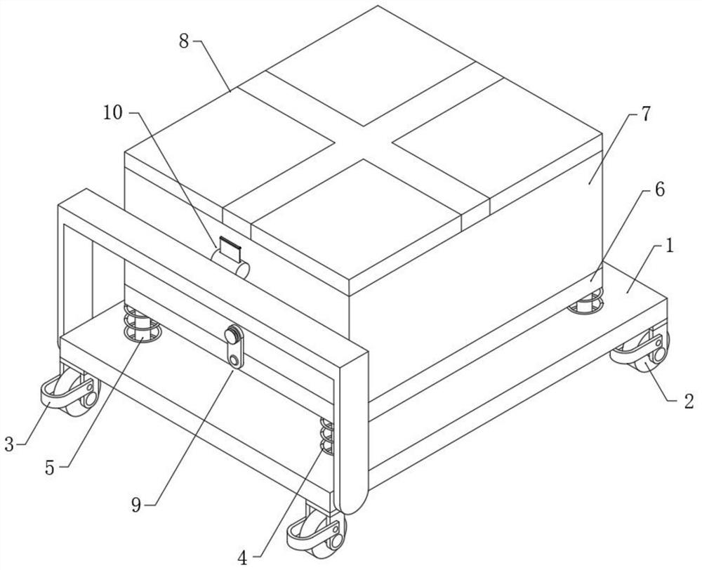
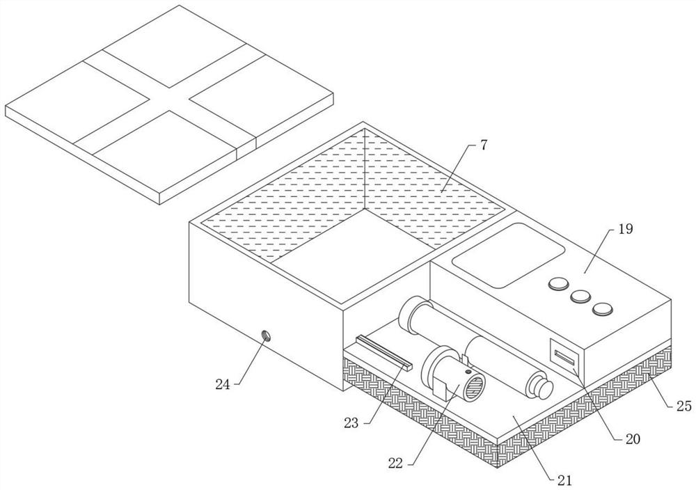
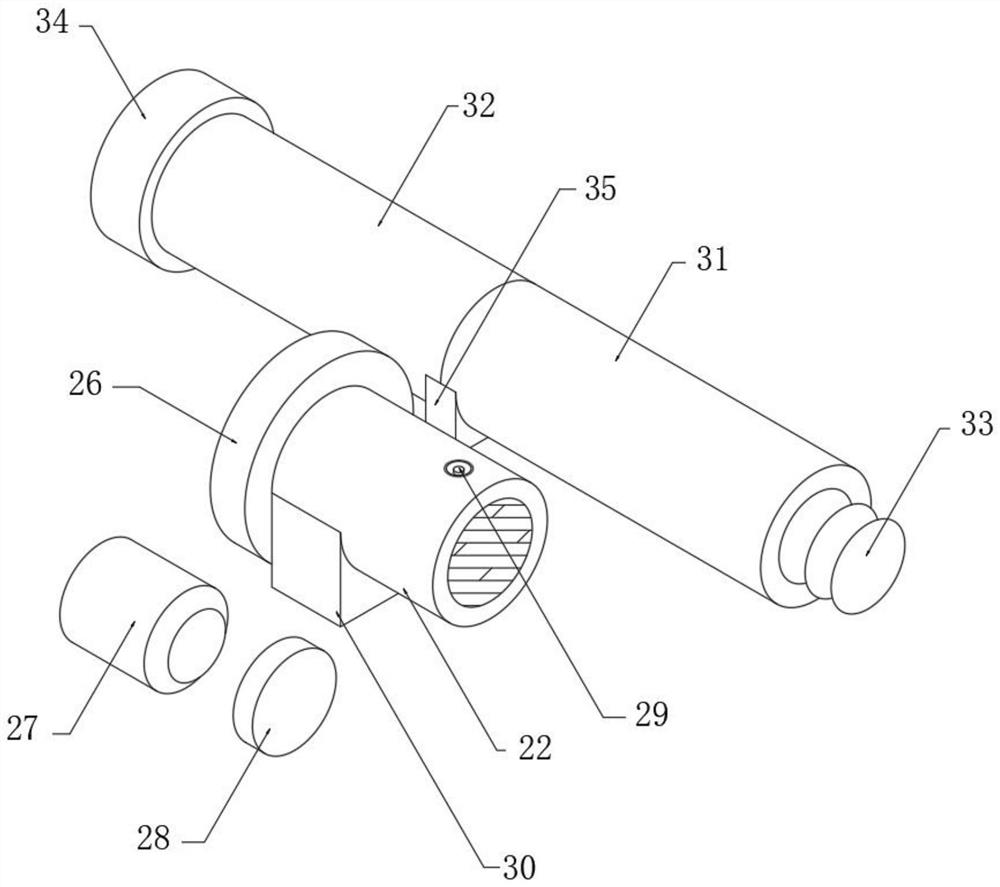
[0026] see Figure 1-6 , the invention provides a technical scheme of a copper ore sampling and analysis device:

[0027] according to Figure 1-6 As shown, including the carrier plate 1, the middle part of the top of the carrier plate 1 is fixedly connected with a vibration-damping bottom plate 6 through a vibration-damping structure, the top of the vibration-damping bottom plate 6 is fixedly provided with a box body 7, and the opening at the top of the box ...


PUM


Abstract

The invention discloses a copper ore sampling analysis device, comprising a carrier plate. A vibration reduction bottom plate is fixedly connected to the middle of the top end of the carrier plate through a vibration reduction structure, a box body is fixedly arranged at the top end of the vibration reduction bottom plate, a protective cover is movably connected to an opening in the top end of thebox body, and two connecting rods are rotatably connected to one side of the carrier plate. One end of each of the two connecting rods is fixedly connected with the two ends of the corresponding holding rod, and the first sampling pipe and the second sampling pipe are in threaded connection through a driving structure composed of the first sampling pipe, the second sampling pipe, the threaded connector, the steel rotary disc, the aluminum outer barrel, the motor, the storage battery and the connecting disc. The first sampling pipe is in threaded connection with the connecting disc through thethreaded connector, the steel rotary disc is in threaded connection with the second sampling pipe and the first sampling pipe, segmented storage of the sampling pipes is facilitated, meanwhile, copper ore can be sampled more deeply through superposition of the first sampling pipe and the second sampling pipe, and the sampling precision is better.

Description

technical field [0001] The invention relates to an analyzing device, in particular to a copper ore sampling and analyzing device, which belongs to the technical field of copper ore sampling. Background technique [0002] Copper ore refers to the general term for available copper-containing natural mineral aggregates. Copper ore is generally an aggregate composed of copper sulfide or oxide and other minerals. It reacts with sulfuric acid to form blue-green copper sulfate, an industrial mineral of copper. There are: natural copper ﹑ chalcopyritechalcocite ﹑ tetrahedrite ﹑ azurite ﹑ malachite, etc. There are more than 280 kinds of copper-bearing minerals that have been found, and only 16 are the main ones. The main ones mined in China are brass ore (compounds of copper, sulfur and iron), followed by chalcocite and bornite; [0003] Chinese Patent No. CN201910908110.0 proposes a sampling device for modern agricultural soil testing. The invention uses the first electric push ...

Claims


Application Information

Patent Timeline
Patent Type & Authority Applications(China)
IPC IPC(8): G01N1/08G01N33/24
CPCG01N1/08G01N33/24
Inventor 钱涛
Owner 钱涛
Learn More