Eureka AIR delivers breakthrough ideas for toughest innovation challenges, trusted by R&D personnel around the world.

Electrical systems

A technology of electrical systems and circuits, applied in the field of electrical systems

Pending Publication Date: 2021-03-12
ROLLS ROYCE PLC
View PDF0 Cites 0 Cited by
  • Summary
  • Abstract
  • Description
  • Claims
  • Application Information

AI Technical Summary

Problems solved by technology

Research suggests possible extended component life and improved fuel consumption rates, which could be significant on short missions

Method used


Image

  • Electrical systems
  • Electrical systems
  • Electrical systems

Examples


Embodiment Construction

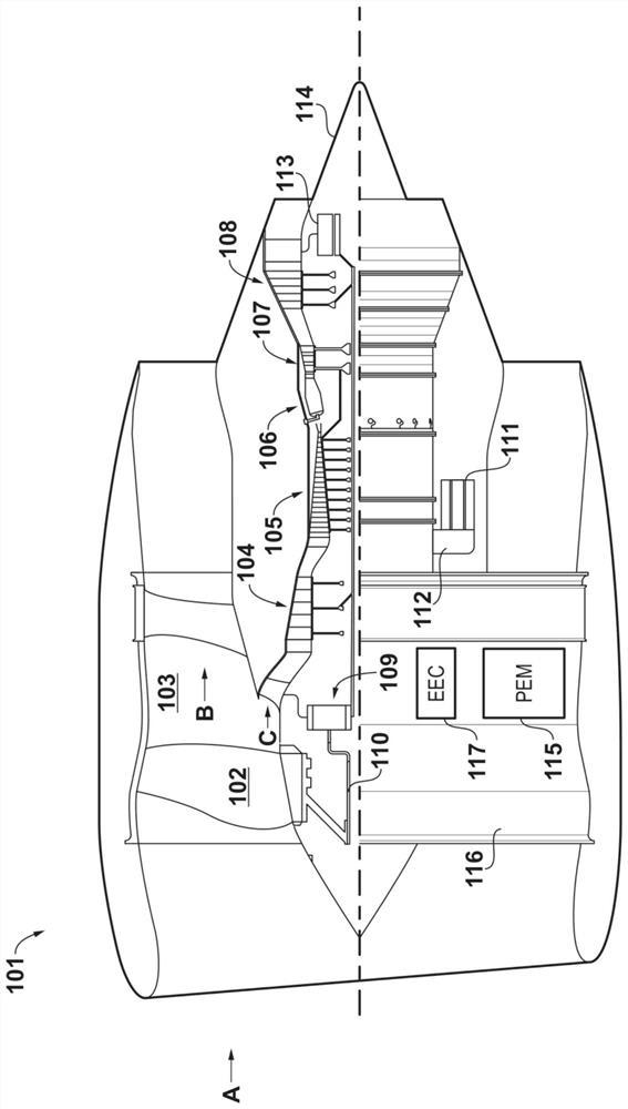
[0074] figure 1

[0075] The general arrangement of an engine 101 for an aircraft is shown in figure 1 middle. In this embodiment, the engine 101 has a turbofan configuration and thus includes a ducted fan 102 which receives intake air A and produces two pressurized flows: a bypass flow B passing axially through a bypass duct 103 and an incoming Core flow C of the core gas turbine.

[0076] The core gas turbine includes a low pressure compressor 104 , a high pressure compressor 105 , a combustor 106 , a high pressure turbine 107 and a low pressure turbine 108 in axial series.

[0077] In operation, the core stream C is compressed by the low pressure compressor 104 and then directed into the high pressure compressor 105 for further compression. Compressed air discharged from the high pressure compressor 105 is directed into a combustor 106 where the compressed air is mixed with fuel and the mixture is combusted. The resulting hot combustion products then expand through a...


PUM


Abstract

Electrical systems for connecting rotary electric machines with gas turbine spools are provided. One such electrical system comprises: a first rotary electric machine mechanically coupled with a firstgas turbine spool and a second rotary electric machine mechanically coupled with a second gas turbine spool, each said electric machine having an identical even number N>=4 of phases, each phase having a respective index n=(1-N), and each phase comprising an identical number P>=1 of coils wound in a P-plex configuration in which adjacent phases are radially separated by 2 Phi / NP mechanical radians; a first set of N bidirectional converter circuits for conversion of alternating current (ac) to and from direct current (dc), each converter circuit having a respective index n and being connectedwith the P coils in the nth phase of the first rotary electric machine; and a second set of N bidirectional converter circuits for conversion of ac to and from dc, each converter circuit having a respective index n and being connected with the P coils in the nth phase of the second rotary electric machine. For all n, a dc side of the nth converter circuit in said first set is connected with a dc side of the nth converter circuit in said second set to facilitate dc power transfer between the first gas turbine spool and the second gas turbine spool.

Description

technical field [0001] The present disclosure relates to electrical systems for connecting electric rotating machines to rotating machines, such as gas turbine slide valves. Background technique [0002] In aerospace, more electric engines (MEE) and more electric aircraft (MEA) concepts are being advocated to drastically reduce the fuel consumption and complexity they bring. For example, one known aircraft configuration includes in its engine an electric machine capable of functioning as both a motor and a generator to facilitate the generation of electrical power during flight and also to facilitate starting of the engine and removal of the air turbine starter. remove. One engine configuration of this known aircraft includes such an electric machine coupled to a high pressure spool valve of a dual spool turbofan. Another configuration includes such a motor coupled to the medium pressure spool of a three spool turbofan. [0003] However, maintenance experience has shown t...

Claims


Application Information

Patent Timeline
IPC IPC(8): H02K11/04H02K11/30H02K7/14H02K7/18F02C6/00B64D27/02
CPCH02K11/30H02K7/14H02K7/183F02C6/00B64D27/02B64D2027/005H02J1/102F01D15/10F02C7/26F01D19/00F05D2220/76Y02T50/50Y02T50/60H02J2310/44F02C3/113F02C7/36H02J3/144H02J3/14H02M1/10
Inventor 大卫·F·布鲁克斯格雷厄姆·P·布鲁斯斯蒂芬·M·赫斯本德
Owner ROLLS ROYCE PLC
Why Eureka
Eureka Blog
Learn More