Sludge drying treatment system for water conservancy and hydropower engineering and operation method thereof

A sludge drying, water conservancy and hydropower technology, applied in the direction of water/sludge/sewage treatment, sludge treatment, water/sewage treatment, etc., can solve the problems of inconvenient sewage filtration and purification, sewage impurities, turbidity, etc. The height of the canopy is convenient for blocking rain and the effect of adjusting the height of the canopy

Active Publication Date: 2021-03-16
保定沛绿水利工程设计有限公司
View PDF4 Cites 4 Cited by
  • Summary
  • Abstract
  • Description
  • Claims
  • Application Information

AI Technical Summary

Problems solved by technology

[0005] Although most of the mud scrapers on the market can effectively remove the soil in the sewage, due to the large amount of impurities and turbidity in the sewage, some small molecules in the sewage The impurities cannot be filtered out, and it is not convenient to further filter and purify the sewage. Therefore, it is necessary to improve the existing equipment to meet the needs of sewage treatment.
[0006] Twin-shaft mixers are widely used in enterprises. Enterprises can mix products through twin-shaft mixers, saving manpower consumption. At the same time, with the continuous development of technology With the development, the twin-shaft mixer is also constantly innovating. There will be many types of twin-shaft mixers on the market, and the structure is relatively large, but some twin-shaft mixers lack a structure that facilitates the installation of the device. improve on the basis of
[0007] Although there are many types and quantities of exhaust gas spray towers on the market, they have the following disadvantages: exhaust gas spray towers do not have the ability to collect rainwater As a result, the water level of the water tank of the exhaust gas spray tower cannot be observed in time and the inside of the water tank of the exhaust gas spray tower is not convenient for cleaning and maintenance

Method used


Image

  • Sludge drying treatment system for water conservancy and hydropower engineering and operation method thereof
  • Sludge drying treatment system for water conservancy and hydropower engineering and operation method thereof
  • Sludge drying treatment system for water conservancy and hydropower engineering and operation method thereof

Examples


Embodiment 1

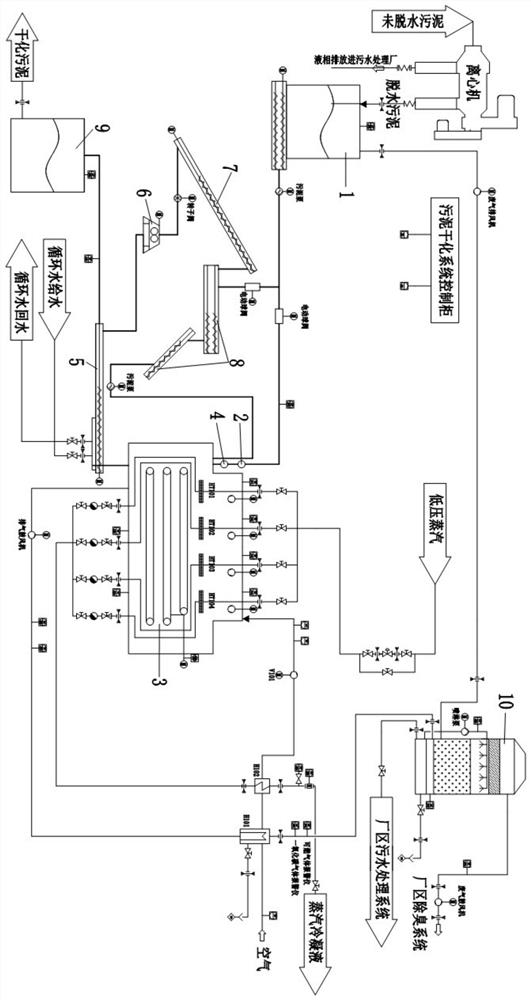
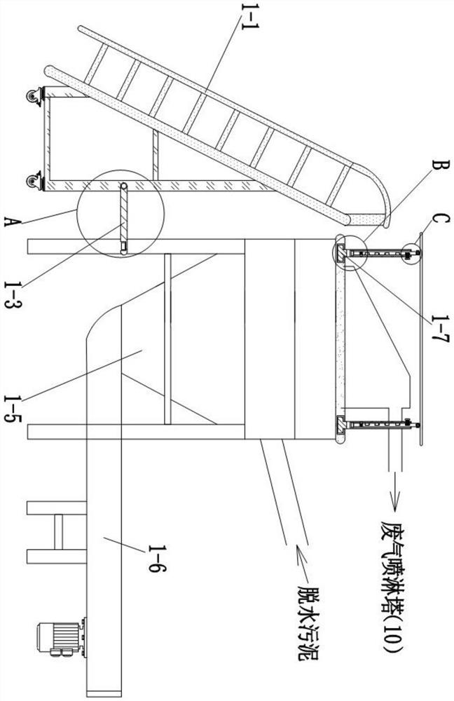
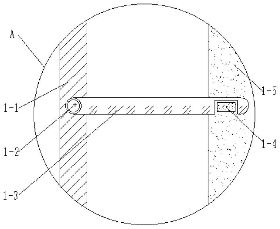
[0073] Wet sludge silo 1 with double-axis screw conveyor at the bottom, including ladder frame 1-1, rotating shaft 1-2, rotating rod 1-3, buckle block 1-4, body 1-5, and double-axis screw conveyor 1-6, card block 1-7, fixed rod 1-8, bullet block 1-9, spring 1-10, inner rod 1-11, limit block 1-12, adjustment bolt 1-13, card bolt 1- 14. The inserting block 1-15 and the canopy 1-16 are connected with a rotating shaft 1-2 on the surface of the ladder frame 1-1.

[0074] One end of the rotating shaft 1-2 is connected with a rotating rod 1-3, and one end of the rotating rod 1-3 is connected with a buckle 1-4. There is a groove at one end of the shaft, the size of the inner wall of the groove at one end of the buckle block 1-4 and the rotating rod 1-3 coincides with each other, and the rotating shaft 1-2 forms a rotating engagement through the joint of the rotating rod 1-3 and the buckle block 1-4 structure, it is convenient to fix the ladder frame 1-1 and the body 1-5, so that it i...

Embodiment 2

[0077] Mud distribution device 2, including foot pad 2-1, bearing 2-2, threaded rod 2-3, support rod 2-4, feeder 2-5, fixed block 2-6, inserting 2-7, the first Spring 2-8, limit block 2-9, buckle 2-10, cover plate 2-11, rotating shaft 2-12, body 2-13, connecting block 2-14, second spring 2-15, pressing block 2 -16 and the manipulator 2-17, the top of the foot pad 2-1 is connected with a bearing 2-2, the inner wall of the bearing 2-2 is welded with a threaded rod 2-3, the outer wall of the threaded rod 2-3 is a threaded structure, and the threaded rod 2-3 forms a rotational connection between the bearing 2-2 and the foot pad 2-1, and forms a threaded connection between the threaded rod 2-3 and the support rod 2-4. By rotating the threaded rod 2-3, the device can be The height of the feeder 2-5 is adjusted, the threaded rod 2-3 is connected through the inside of the support rod 2-4, the top of the support rod 2-4 is welded with the feeder 2-5, and the feeder 2-5 The surface of ...

Embodiment 3

[0080] The sludge noodle forming machine 4 includes a body 4-1, a fixed rod 4-2, a threaded rod 4-3, a rotating block 4-4, a connecting column 4-5, a clamping block 4-6, a scraper 4-7, Transmission belt 4-8, mounting plate 4-9, connecting block 4-10, rotating shaft 4-11, movable rod 4-12, mounting block 4-13, docking block 4-14, spring 4-15 and linkage block 4 -16, the bottom of the body 4-1 is connected with a fixed rod 4-2.

[0081] The fixed rod 4-2 is provided with a threaded rod 4-3 inside, and the threaded rod 4-3 is vertically connected to the inside of the connecting column 4-5, and the size of the outer wall of the threaded rod 4-3 matches the size of the inner wall of the connecting column 4-5, and The connection between the threaded rod 4-3 and the connecting column 4-5 forms a threaded connection structure, which plays a role in making the connecting column 4-5 move under the rotation of the threaded rod 4-3, and the bottom of the threaded rod 4-3 is connected with...


PUM


Abstract

Provided are a sludge drying treatment system for water conservancy and hydropower engineering and an operation method thereof. Non-dewatered sludge is separated into liquid-phase sewage and dewateredsludge through a centrifugal machine, the liquid-phase sewage is discharged into a sewage treatment plant to be treated, the dewatered sludge is conveyed to a wet sludge bin, waste gas is conveyed into a waste gas spraying tower through a discharging pipeline to be treated, and the waste gas treated by the spraying tower is conveyed into a factory deodorization system through a waste gas air blower; the wet sludge material is conveyed to a sludge distributor through a double-shaft screw conveyor, the uniformly distributed and spread sludge is cut into noodle shapes by a sludge noodle shape forming machine, and the noodle-shaped dried sludge is scraped by a sludge scraper; a cooling screw conveyor cools the noodle-shaped sludge with waste heat, and the completely cooled noodle-shaped sludge is fed into a dry sludge bin and finally fed into dried sludge to be treated; the noodle-shaped sludge which is not completely cooled is conveyed into a crusher, mixed, and conveyed into the sludgedistributor again for circulation.

Description

technical field [0001] The invention relates to the technical field of water conservancy and hydropower engineering, in particular to a sludge drying treatment system for water conservancy and hydropower engineering and an operating method thereof. Background technique [0002] Although there are many types and quantities of wet sludge silos with biaxial screw conveyors at the bottom on the market, the wet sludge silos with biaxial screw conveyors at the bottom have such shortcomings: the existing sewage Due to its huge size, the mud silo is usually placed outdoors. However, the top of the sludge silo is exposed, and the user cannot work in rainy weather when maintaining the sludge silo. Therefore, a rain-shielding device is needed. Therefore, the wet sludge silo that the current bottom is provided with a biaxial screw conveyor is improved. [0003] However, when most of the mud distributors on the market are processing materials, because the feeder does not have a machine ...

Claims


Application Information

Patent Timeline
Patent Type & Authority Applications(China)
IPC IPC(8): C02F11/127B01D53/18B01D53/14B01D47/06B01D36/02C02F1/00E03B3/02
CPCC02F11/127B01D53/18B01D53/1412B01D47/06B01D36/02C02F1/001E03B3/02C02F2103/001Y02P70/10Y02A20/108
Inventor 冉昊冬
Owner 保定沛绿水利工程设计有限公司
Why Eureka
Try Eureka