
High-temperature pressure sensor packaging structure

A pressure sensor and packaging structure technology, applied in the measurement of fluid pressure, instruments, measuring devices, etc., can solve the difficulty of sintering ceramic and slurry with increased size, the conductivity of ceramic shell is not as good as that of metal shell, high temperature pressure sensor and packaging failure, etc. problems, to achieve the effect of ensuring performance, good air tightness, and low sintering difficulty

Pending Publication Date: 2021-03-16
ZHONGBEI UNIV
View PDF0 Cites 1 Cited by
  • Summary
  • Abstract
  • Description
  • Claims
  • Application Information

AI Technical Summary

Problems solved by technology

Among them, the following two issues are mainly considered: 1. The thermal stress problem caused by the difference in thermal expansion coefficient between the package shell material, ceramic material and high-temperature pressure sensor, which may lead to direct failure of the high-temperature pressure sensor and package or correct testing signal interference
Of course, there are also processing difficulties in order to realize the appealing packaging solution. For example, the small size of the packaging structure will increase the difficulty of sintering ceramics and paste.
However, high-temperature pressure sensors generally work in harsh and complex high-temperature environments. If all ceramic materials are used, the packaging cost will be extremely expensive, and the conductivity of the ceramic shell is not as good as that of the metal shell, and there is no way to provide static protection for the internal chip. The ability to resist electromagnetic interference is poor, and there are hidden dangers in reliability

Method used


Image

  • High-temperature pressure sensor packaging structure
  • High-temperature pressure sensor packaging structure
  • High-temperature pressure sensor packaging structure

Examples


Embodiment Construction

[0029] Embodiments of the present invention are described in detail below, examples of which are shown in the drawings, wherein the same or similar reference numerals designate the same or similar elements or elements having the same or similar functions throughout. The embodiments described below by referring to the figures are exemplary only for explaining the present invention and should not be construed as limiting the present invention.

[0030] In the description of the present invention, it should be understood that the orientations or positional relationships indicated by the terms "center", "upper", "lower", "front", "rear", "left", "right" etc. are based on the attached The orientation or positional relationship shown in the figure is only for the convenience of describing the present invention and simplifying the description, and does not indicate or imply that the referred combination or element must have a specific orientation, be constructed and operated in a spec...


PUM


Abstract

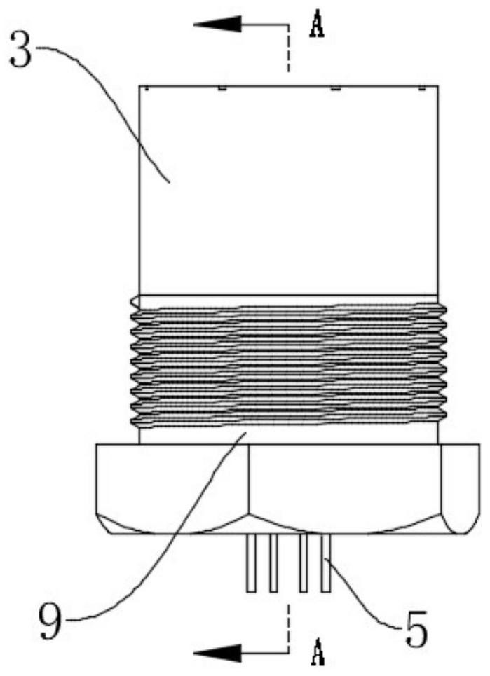
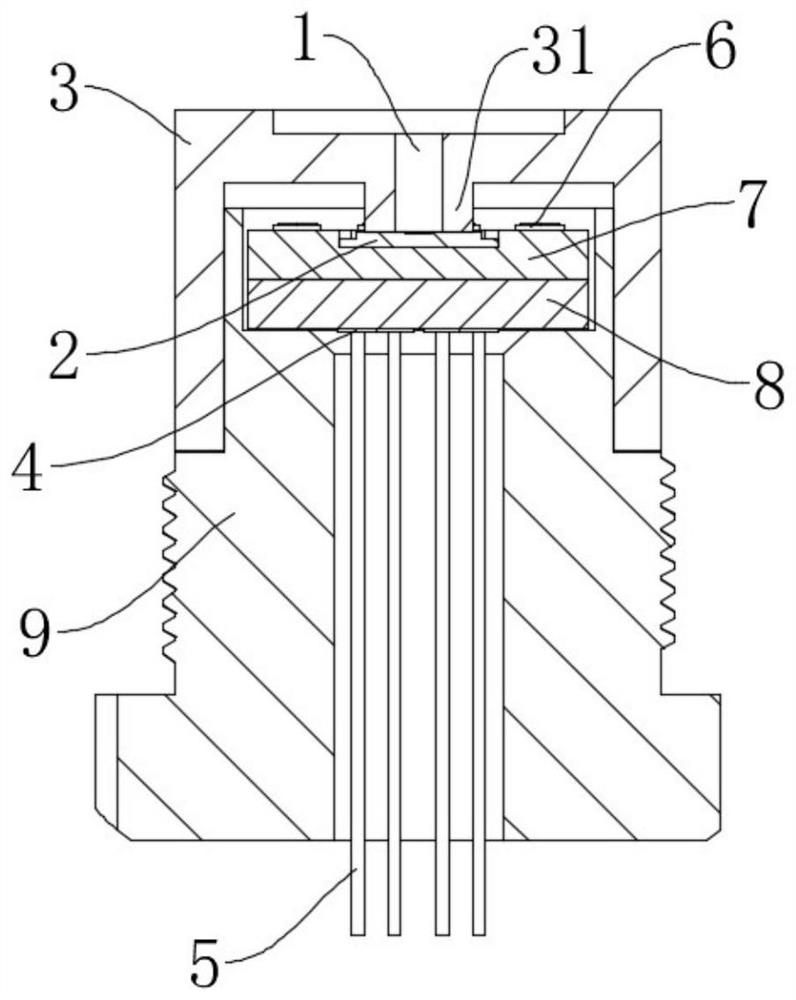
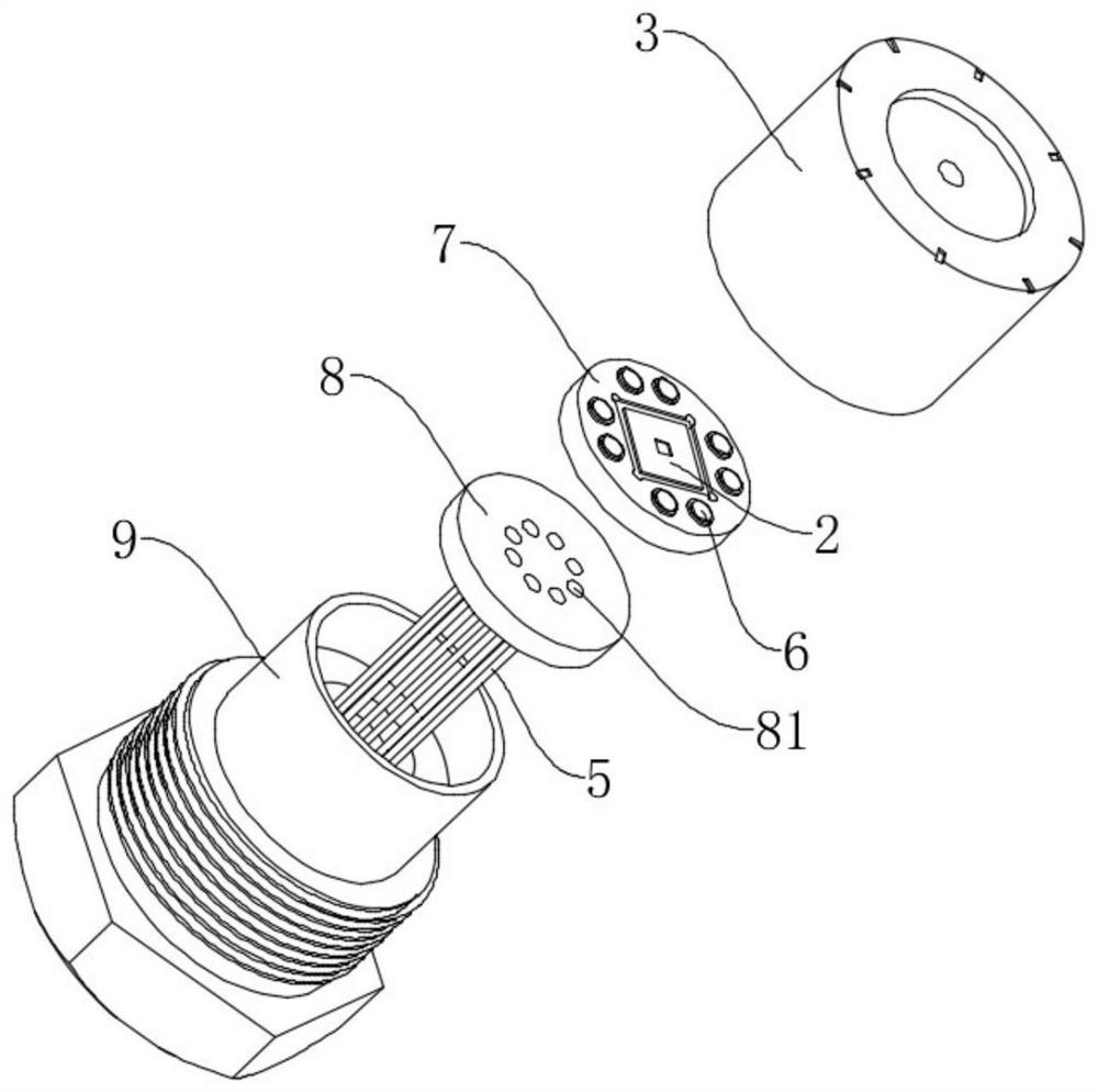
A high-temperature pressure sensor packaging structure comprises a packaging base, a packaging end cover, a sensor chip and a ceramic substrate assembly, a first mounting groove used for containing the ceramic substrate assembly is formed in the packaging base, the ceramic substrate assembly is arranged in the first mounting groove, the sensor chip is arranged on the ceramic substrate assembly, the packaging end cover is buckled on the packaging base, and the sensor chip and the ceramic substrate assembly are sealed in a containing space formed by the packaging base and the packaging end cover. The beneficial effects of the invention are that the second through holes in the second ceramic substrate can effectively reduce the distribution of the rear ends of the lead pins through reducing the layout range, the chamfers on the third through holes can reduce the welding area so as to reduce the thermal stress at a high temperature, and the circular grooves formed in the four corners of the second installation groove can enable the solder not to be accumulated during compression sintering. The structure is low in sintering difficulty, good in airtightness, high in packaging precision and capable of bearing severe environments such as high temperature and high pressure, and performance of the pressure sensor in high-temperature environments is guaranteed.

Description

technical field [0001] The invention relates to the field of MEMS sensor packaging, in particular to a high-temperature pressure sensor packaging structure. Background technique [0002] Graphene materials are very promising materials for high-temperature and harsh conditions. Some domestic and foreign studies have shown that graphene can withstand high temperatures of 3000 °C in an oxygen-free environment, but there is a lack of corresponding packaging to develop the application of graphene-related devices in the high-temperature field. Therefore, if there is no corresponding reliable packaging structure, only graphene devices will not work at high temperatures. [0003] Under high temperature conditions, there are some problems that need to be considered. First, the materials of each part must be resistant to high temperature; second, the thermal expansion of each part must match; third, each part will not change its properties due to chemical reactions between each part; ...

Claims


Application Information

Patent Timeline
Patent Type & Authority Applications(China)
IPC IPC(8): G01L19/06G01L19/14
CPCG01L19/0681G01L19/147G01L19/148
Inventor 王俊强李孟委陈绪文
Owner ZHONGBEI UNIV
Learn More