
Low-melting-point high-latent-heat phase change and energy storage material as well as preparation method thereof

A phase change energy storage material with a low melting point technology, applied in the field of phase change energy storage, can solve the problems of reducing the latent heat of phase change of materials, low latent heat, and reducing the recycling performance of materials

Pending Publication Date: 2021-03-19
GRIMAT ENG INST CO LTD
View PDF9 Cites 3 Cited by
  • Summary
  • Abstract
  • Description
  • Claims
  • Application Information

AI Technical Summary

Problems solved by technology

[0006] The latent heat of phase change materials disclosed so far with a phase transition temperature of around 100°C is relatively low. Studies have found that high addition of In element will greatly reduce the latent heat of phase transition of the material.
However, although the addition of a large amount of Bi and Sn will increase the latent heat of phase transformation, it will cause the alloy to have a melting characteristic of multiple melting points during the melting process, which greatly reduces the recycling performance of the material.
Patent Publication No. CN103146975A discloses a lead-free low-temperature alloy with a melting point of 116±2°C and its preparation method. Patent Publication No. CN103146976A discloses a lead-free low-temperature alloy with a melting point of 100±2°C and its preparation method. Although the above low-melting point alloys do not contain environmentally harmful elements and have a narrow melting range, they have low latent heat of phase transformation and less heat storage during actual use.

Method used


Image

  • Low-melting-point high-latent-heat phase change and energy storage material as well as preparation method thereof
  • Low-melting-point high-latent-heat phase change and energy storage material as well as preparation method thereof
  • Low-melting-point high-latent-heat phase change and energy storage material as well as preparation method thereof

Examples


Embodiment 1

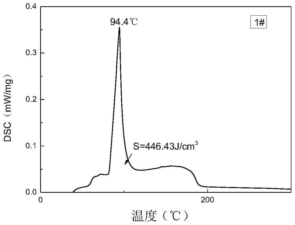
[0027] A method for a high latent heat phase change energy storage material, comprising the following steps:

[0028] (1) In this embodiment, the alloy composition and weight ratio of eutectic melting characteristic with low melting point and high latent heat are as follows: Sn 10%, In 10%, Bi 80%.

[0029] (2) According to the above proportions, take Sn, In and Bi elemental metal blocks with a corresponding mass of 99.995% purity, ultrasonically clean them in 95% alcohol solution for 5 minutes, and put them into a drying oven for drying. Put the dried metal element into the vacuum melting furnace, close the vacuum melting furnace and carry out vacuum treatment to make the vacuum pressure in the vacuum melting furnace reach -0.1MPa, and then fill the vacuum melting furnace with argon to normal pressure.

[0030] (3) Put the simple metal into the crucible, and heat it to 400°C with a heating furnace at a heating rate of 20°C / min in an environment isolated from water and oxygen,...

Embodiment 2

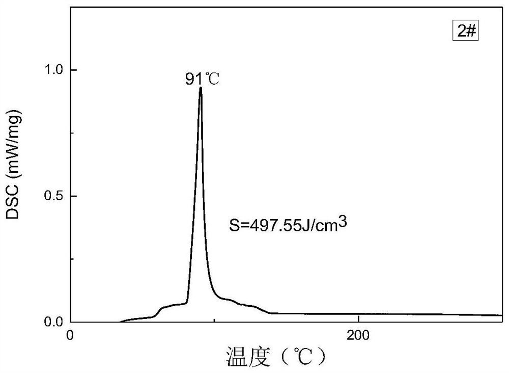
[0033]A method for a high latent heat phase change energy storage material, comprising the following steps:

[0034] (1) In this embodiment, the alloy composition and weight ratio of eutectic melting characteristic with low melting point and high latent heat are as follows: Sn 20%, In 20%, Bi 60%.

[0035] (2) According to the above proportions, take Sn, In and Bi elemental metal blocks with a corresponding mass of 99.995% purity, ultrasonically clean them in 95% alcohol solution for 5 minutes, and put them into a drying oven for drying. Put the dried metal element into the vacuum melting furnace, close the vacuum melting furnace and carry out vacuum treatment to make the vacuum pressure in the vacuum melting furnace reach -0.1MPa, and then fill the vacuum melting furnace with argon to normal pressure.

[0036] (3) Put the simple metal into the crucible, and heat it to 400°C with a heating furnace at a heating rate of 20°C / min in an environment isolated from water and oxygen, ...

Embodiment 3

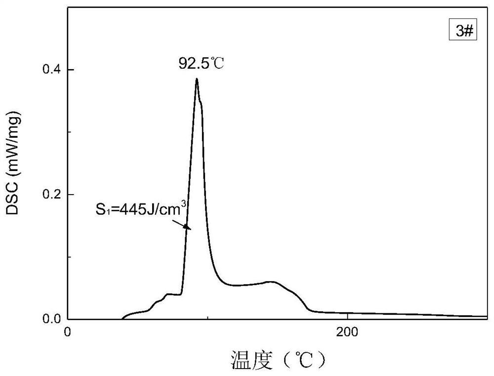
[0039] A method for a high latent heat phase change energy storage material, comprising the following steps:

[0040] (1) In this embodiment, the alloy composition and weight ratio of eutectic melting characteristic with low melting point and high latent heat are as follows: Sn 20%, In 10%, Bi 70%.

[0041] (2) According to the above proportions, take Sn, In and Bi elemental metal blocks with a corresponding mass of 99.995% purity, ultrasonically clean them in 95% alcohol solution for 5 minutes, and put them into a drying oven for drying. Put the dried metal element into the vacuum melting furnace, close the vacuum melting furnace and carry out vacuum treatment to make the vacuum pressure in the vacuum melting furnace reach -0.1MPa, and then fill the vacuum melting furnace with argon to normal pressure.

[0042] (3) Put the simple metal into the crucible, and heat it to 400°C with a heating furnace at a heating rate of 20°C / min in an environment isolated from water and oxygen,...


PUM

PropertyMeasurementUnit
Melting temperatureaaaaaaaaaa

Abstract

The invention relates to a low-melting-point high-latent-heat phase change and energy storage material as well as a preparation method thereof. The material is a low-melting-point high-latent-heat alloy with eutectic melting characteristics, and comprises the following components in percentage by weight: 10-25% of In, 10-25% of Sn, 0-4% of Ga, 0-4% of Zn and the balance of Bi. During preparation,the components are firstly weighed in proportion, indium with purity higher than 99.995wt%, tin, gallium, zinc and bismuth are put into a vacuum smelting furnace, and steps of smelting, stirring, pouring and cooling are performed under conditions of isolating air to control water and oxygen content in the vacuum smelting furnace. The material has a smelting temperature ranging from 90 DEG C to 100DEG C, and has latent heat of 420J / cm3 or more per unit volume. The alloy components are high volume phase change and latent heat, and the alloy is free of poisonous and harmful elements, so that thelow-melting-point high-latent-heat phase change and energy storage material can be widely applied to electronic equipment thermal management.

Description

technical field [0001] The invention relates to a low melting point high latent heat phase change energy storage material and a preparation method thereof, in particular to a low melting point phase change heat storage alloy with eutectic melting characteristics and a preparation method thereof, belonging to the field of phase change energy storage. Background technique [0002] With the development of electronic packaging technology towards high frequency, high speed, multi-function, high performance, small size and high reliability, device heat dissipation is an important technical bottleneck restricting the performance of electronic products. Facing the complex heat dissipation environment of electronic devices, high-power components cannot achieve rapid and effective temperature control through active heat dissipation methods such as air cooling and water cooling. In the case of inability to effectively dissipate heat, phase change materials with high thermal conductivit...

Claims


Application Information

Patent Timeline
IPC IPC(8): C22C12/00C22C30/04C22C30/06C22C1/02C22B9/04C09K5/06
CPCC09K5/063C22B9/04C22C1/02C22C12/00C22C30/04C22C30/06
Inventor 郭宏杜世杰谢忠南张习敏黄树晖米绪军
Owner GRIMAT ENG INST CO LTD
Learn More