Ethylene cracking furnace and ethylene cracking method

An ethylene cracking furnace, ethylene cracking technology, applied in the directions of cracking, hydrocarbon cracking to hydrocarbon, non-catalytic thermal cracking, etc., can solve the problems of coking, reduce heat exchange area, etc. Effects across temperature

Inactive Publication Date: 2021-03-23
SINOPEC ENG +1
View PDF5 Cites 1 Cited by
  • Summary
  • Abstract
  • Description
  • Claims
  • Application Information

AI Technical Summary

Problems solved by technology

[0006] The purpose of the present invention is to provide an ethylene cracking furnace, which proposes different arrangements for the convection section, solves the problem that raw materials with different properties, especially heavy raw materials, may coke in the convection section, and at the same time makes more reasonable use of the waste heat of the flue gas , reduce the heat exchange area and save investment

Method used


Image

  • Ethylene cracking furnace and ethylene cracking method
  • Ethylene cracking furnace and ethylene cracking method
  • Ethylene cracking furnace and ethylene cracking method

Examples


Embodiment 1

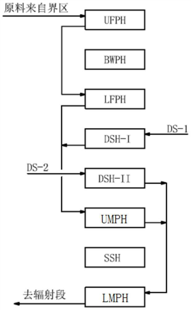
[0046] Convection section 2 adopts such as figure 2 The convection section arrangement shown. The convection section is divided into eight sections from top to bottom, which are: upper raw material preheater (UFPH), boiler feed water preheater (BWPH), lower raw material preheater (LFPH), primary dilution steam superheater (DSH -I), secondary dilution steam superheater (DSH-II), upper mixing preheater (UMPH), super high pressure steam superheater (SSH) and lower mixing preheater (LMPH). The dilution steam from the boundary area is divided into primary steam (DS-1) and secondary steam (DS-2). After the primary steam (DS-1) is overheated in the primary dilution steam superheater (DSH-I), it The raw materials from the raw material preheater (LFPH) are mixed, and the obtained oil-gas mixture enters the upper mixing preheater (UMPH) for superheating, and the secondary steam (DS-2) is superheated in the secondary dilution steam superheater (DSH-Ⅱ) , the superheated dilution steam ...

Embodiment 2

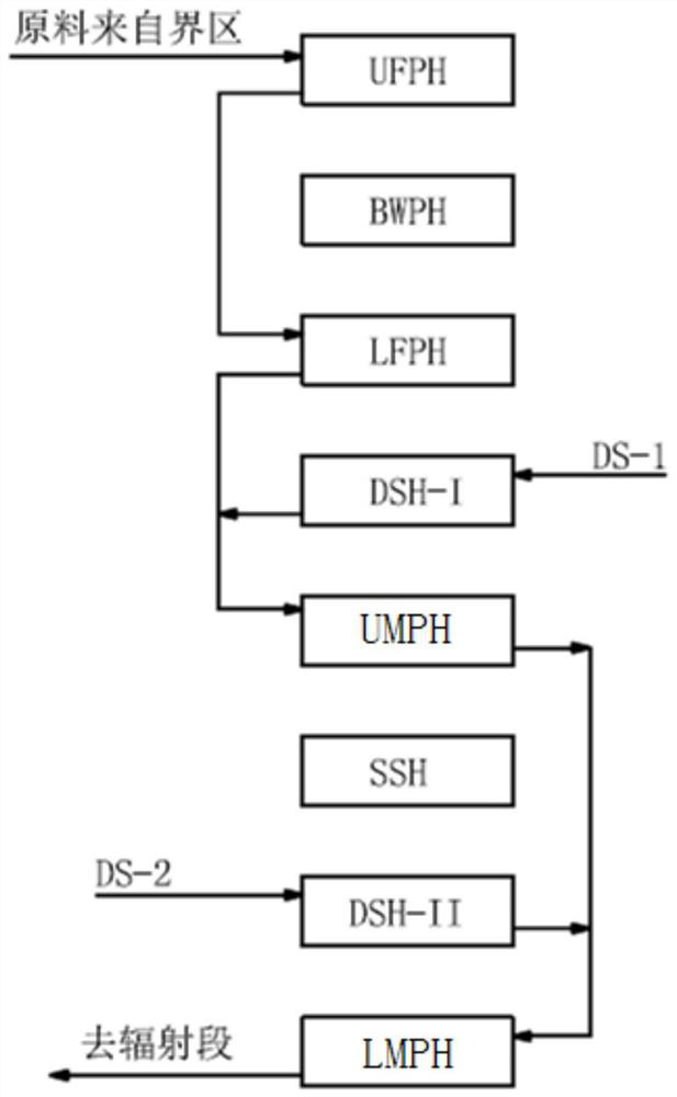
[0048] Convection section 2 adopts such as image 3 The convection section arrangement shown. The convection section is divided into eight sections from top to bottom, which are: upper raw material preheater (UFPH), boiler feed water preheater (BWPH), lower raw material preheater (LFPH), primary dilution steam superheater (DSH -I), upper mixing preheater (UMPH), super high pressure steam superheater (SSH), secondary dilution steam superheater (DSH-II) and lower mixing preheater (LMPH). The dilution steam from the boundary area is divided into primary steam (DS-1) and secondary steam (DS-2). After the primary steam (DS-1) is overheated in the primary dilution steam superheater (DSH-I), it The raw materials from the raw material preheater (LFPH) are mixed, and the obtained oil-gas mixture enters the upper mixing preheater (UMPH) for superheating, and the secondary steam (DS-2) is superheated in the secondary dilution steam superheater (DSH-Ⅱ) , the superheated dilution steam i...

Embodiment 3

[0050] Convection section 2 adopts such as Figure 4 The convection section arrangement shown. The convection section is divided into eight sections from top to bottom, which are: upper raw material preheater (UFPH), boiler feed water preheater (BWPH), lower raw material preheater (LFPH), primary dilution steam superheater (DSH -I), secondary dilution steam superheater (DSH-II), upper mixing preheater (UMPH), super high pressure steam superheater (SSH) and lower mixing preheater (LMPH). After the dilution steam (DS) from the boundary area is superheated in the primary dilution steam superheater (DSH-I), part of the steam is mixed with the raw material from the lower raw material preheater (LFPH), and the obtained oil-gas mixture enters the upper mixing together The preheater (UMPH) is superheated, and the remaining steam is superheated in the secondary dilution steam superheater (DSH-Ⅱ), and the superheated dilution steam is mixed with the hydrocarbon mixture at the outlet of...


PUM


Abstract

The invention belongs to the field of petrochemical engineering, and relates to an ethylene cracking furnace and an ethylene cracking method. The ethylene cracking furnace comprises a high-pressure steam pocket, a convection section, a radiation section, a quenching boiler and a combustor, a plurality of radiation furnace tube groups are arranged in the radiation section, and each radiation furnace tube group comprises a plurality of radiation furnace tubes; convection section heat exchange tubes are arranged in the convection section, and the convection section heat exchange tubes are a plurality of heat exchange tube bundles which are horizontally arranged; and the arrangement mode of the multiple heat exchange tube bundles enables the convection section to comprise an upper raw materialpreheater, a boiler feed water preheater, a lower raw material preheater, a primary dilution steam superheater, a secondary dilution steam superheater, an upper mixing preheater, an ultrahigh pressure steam superheater and a lower mixing preheater. Different convection section arrangement schemes are provided, the problem that raw materials with different properties, especially heavy raw materials, may be coked in the convection section is solved, meanwhile, waste heat of flue gas is utilized more reasonably, the heat exchange area is reduced, and investment is saved.

Description

technical field [0001] The invention belongs to the field of petrochemical industry, and more specifically relates to an ethylene cracking furnace and an ethylene cracking method. Background technique [0002] In the ethylene plant, the cracking furnace is the core equipment (such as figure 1 shown). The furnace tubes of the radiant section of the early cracking furnace were arranged horizontally in the radiant section. With the development of cracking technology, since 1964, the first double-sided radiation short residence time cracking furnace with vertical furnace tube structure in the radiant section was developed by Lummus in Germany. Since its launch, several companies engaged in the development of ethylene technology have invested a lot of money and technical force in the development of cracking technology. [0003] In order to adapt to the cracking of raw materials with different properties and avoid coking in the convection section, companies developing various te...

Claims


Application Information

Patent Timeline
Patent Type & Authority Applications(China)
IPC IPC(8): C10G9/20C07C4/04C07C11/04
CPCC10G9/20C07C4/04C10G2400/20
Inventor 何细藕邵晨赵永华郭凡
Owner SINOPEC ENG
Why Eureka
Try Eureka