Static infiltration device for rapid pultrusion of composite material

A technology of pultrusion and composite materials, applied in the direction of coating, etc., can solve problems such as short gel time, limited capacity, complex structure, etc., and achieve the effect of breaking through technical bottlenecks, improving replacement rate, and uniform texture

Active Publication Date: 2021-03-26
QINGDAO HILYWILL ADVANCED MATERIALS TECH
View PDF7 Cites 1 Cited by
  • Summary
  • Abstract
  • Description
  • Claims
  • Application Information

AI Technical Summary

Problems solved by technology

[0002]In the pultrusion process of composite materials, the fiber yarn needs to be impregnated with resin, and then pulled into the mold to solidify and form. Traditional impregnation equipment mainly has two forms: (1) The first type is open impregnation, that is, an impregnation tank with an open upper end, which contains liquid resin. The fiber yarn is pressed into the resin in the tank by some pressure rollers, and pulled out by the traction device. It is clamped with rubber rollers. After removing excess resin, it enters the mold for curing and molding; this kind of dipping tank has a large volume and contains a large amount of resin, so the resin must have a long enough pot life (that is, the gel time of the resin) It must be long enough), otherwise the resin in the dipping tank will gel and cause production to stop during continuous production, so this open dipping tank is mostly used for unsaturated resins, epoxy resins, phenolic resins, etc., and this kind of dipping tank The fiber and yarn capacity of the rubber tank is also relatively limited, and it can pass through several million Tex rovings at a time (Tex, English Tex, referred to as special, formerly known as public support, is a linear density unit), if the production is large For products with a small size, only multiple dipping tanks can be installed in parallel to meet the demand, but this parallel connection takes up a lot of space and has a complicated structure
(2) The second type is a closed dipping box, its structure is usually to add a cavity integrated with the mold at the front end of the pultrusion die, inject the resin into the cavity through the pipeline, and the fiber yarn passes through the cavity When it is in the body, it will be infiltrated, and then enter the mold to solidify and form; the advantage of the closed impregnation box is that the infiltration distance is short, and it is suitable for resins with a short pot life (that is, the resin has a short gel time), such as polyurethane resin, fast type Epoxy resin, etc., the disadvantage is that the fiber can only enter the cavity from a single channel, so the capacity is very limited, and at most several million tex rovings can pass through at a time, and when too many fibers pass through, the limited capacity makes the impregnation quality poor. In addition, there is a big defect: the closed dipping box is only suitable for products with a resin content of 18-25%, such as composite sleepers with a resin content of 40-55%, this structure cannot Be applicable
Composite sleepers are formed by pultrusion molding of continuous glass fiber-reinforced foamed polyurethane. During the production process, limited by the short pot life of the resin, fiber infiltration must be completed within 300 seconds or less. Large (about 10 million tex), so the above two kinds of dipping equipment cannot meet the process requirements. At present, the dipping operation is performed by manual rubbing. Manual operation makes the dipping effect extremely unstable, resulting in a high scrap rate, and the production The efficiency is low, so it is far from meeting the production needs; in addition, due to the limitation of the amount of yarn passing, the manual rubbing and soaking method can generally only produce smaller-sized light sleepers, such as light sleepers for subways, etc., or stick them in pieces. Production of large and heavy-duty sleepers by continuous method

Method used


Image

  • Static infiltration device for rapid pultrusion of composite material
  • Static infiltration device for rapid pultrusion of composite material
  • Static infiltration device for rapid pultrusion of composite material

Examples


Embodiment Construction

[0024] The present invention will be further described below in conjunction with the accompanying drawings and examples.

[0025] The technical solutions in the embodiments of the present invention will be clearly and completely described below. Obviously, the described embodiments are only some of the embodiments of the present invention, but not all of them. Based on the embodiments of the present invention, all other embodiments obtained by those skilled in the art without creative efforts fall within the protection scope of the present invention.

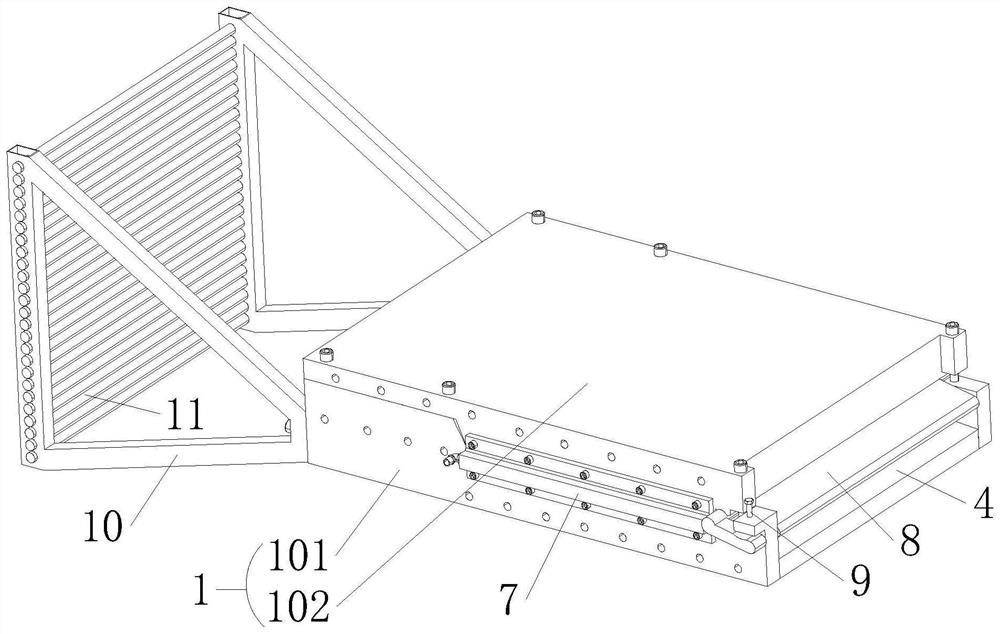
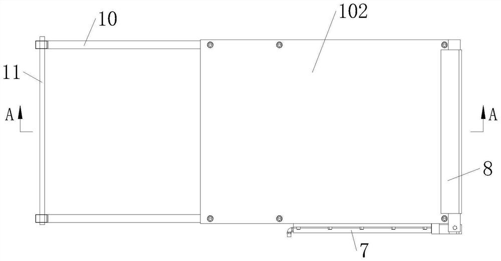
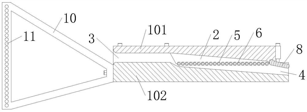
[0026] A static infiltration device for rapid pultrusion molding of composite materials, comprising a box body 1, the box body 1 includes a lower cavity 101, the upper end surface of the lower cavity 101 is open, and the lower cavity 101 An upper cover 102 is installed on the upper end surface; the box body 1 is divided into upper and lower structures, which is convenient for loading and unloading and daily maintenance of the in...


PUM

PropertyMeasurementUnit
diameteraaaaaaaaaa

Abstract

The invention relates to the technical field of railway track material equipment, in particular to a static infiltration device for rapid pultrusion of a composite material. The static infiltration device comprises a box body, a gum dipping cavity is formed in the box body, and a yarn inlet and a yarn outlet are separately formed in two opposite side surfaces of the box body; and a plurality of parallel yarn guide rods are installed in the gum dipping cavity, are arranged in the horizontal direction and are perpendicular to the pultrusion direction of yarn. According to the static infiltrationdevice, a pre-stress jack can be moved, the angle is adjustable, thus, the pre-stress jack is convenient and easy to install, and high safety and high efficiency are achieved.

Description

technical field [0001] The invention relates to the technical field of railway track material equipment, in particular to a static infiltration device for rapid pultrusion molding of composite materials. Background technique [0002] In the pultrusion process of composite materials, the fiber yarn needs to be impregnated with resin, and then pulled into the mold to solidify and form. Traditional dipping equipment mainly has two forms: (1) The first type is open dipping, that is, an upper end Open dipping tank, filled with liquid resin, the fiber yarn is pressed into the resin in the tank by some pressure rollers, pulled out by traction equipment, can be clamped with rubber rollers, after removing excess resin, enter the mold for curing Forming; this kind of dipping tank has a large volume and a large amount of resin, so the resin must have a long enough pot life (that is, the gel time of the resin must be long enough), otherwise, in continuous production, the dipping tank wi...

Claims


Application Information

Patent Timeline
Patent Type & Authority Applications(China)
IPC IPC(8): B29C70/52B29B15/12B29B15/14
CPCB29C70/522B29B15/125B29B15/14
Inventor 张万明王庆明车骁
Owner QINGDAO HILYWILL ADVANCED MATERIALS TECH
Why Eureka
Try Eureka