Rectangular jacking pipe joint concrete pouring method utilizing bin dividing steel plates

A rectangular pipe jacking and concrete technology, which is used in earth-moving drilling, wellbore lining, tunnel lining, etc., can solve the problems of incompact concrete, increase the difficulty of construction, and narrow working space, so as to improve construction efficiency and quality, and reduce costs. The effect of secondary operation strength and improvement of anti-deformation ability

Active Publication Date: 2021-03-26
CHINA RAILWAY 15TH CONSTR BUREAU GRP +1
View PDF5 Cites 0 Cited by
  • Summary
  • Abstract
  • Description
  • Claims
  • Application Information

AI Technical Summary

Problems solved by technology

The shell of the pipe jacking machine with low rigidity cannot bear the load of the overlying soil, resulting in large deformation of the soil, which is not good for the existing underground main structure and nearby ground structures
[0004] The existing technology pipe jacking machine needs to use cast-in-place concrete to seal the annular space of the discarded shell section after the discarded shell section is removed and transported outside, because the prefabricated concrete segment cannot be jacked.
The working space in the rectangular excavation channel is narrow, and it is difficult to install and fix the concrete formwork. The uneven formwork seriously affects the appearance quality of the cast-in-place concrete
The roof of the cast-in-place section is a flat plate structure. When pouring concrete, it is easy to cause the local concrete of the roof to be not dense, and it cannot effectively form a whole with the shell of the pipe jacking machine.
It is difficult to vibrate manually when pouring concrete in the underground closed space, which makes it difficult to guarantee the quality of concrete pouring
[0005] The existing technology adopts the construction scheme of one-time pouring and forming, which needs to use a long flexible distribution pipe to penetrate into the farthest side of the cast-in-place section. The construction personnel cannot accurately grasp the position of the distribution pipe, which increases the difficulty of construction.

Method used


Image

  • Rectangular jacking pipe joint concrete pouring method utilizing bin dividing steel plates
  • Rectangular jacking pipe joint concrete pouring method utilizing bin dividing steel plates
  • Rectangular jacking pipe joint concrete pouring method utilizing bin dividing steel plates

Examples


Embodiment Construction

[0036] The present invention will be described in further detail below in conjunction with the accompanying drawings and specific implementation methods.

[0037] A method for concrete pouring of rectangular pipe jacking joints utilizing sub-silo steel plates of the present invention comprises the following steps:

[0038] Step 1: Preparation before concrete pouring:

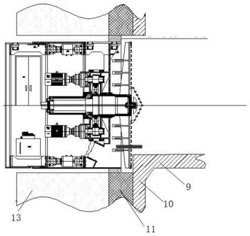
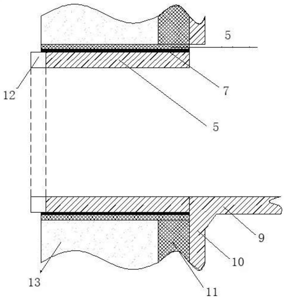
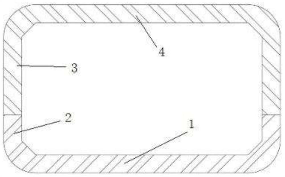
[0039] After all the equipment in the pipe jacking shell 7 has been dismantled and hoisted, hoist the steel formwork to the bottom of the receiving shaft, and then transfer it manually to the cast-in-place section, such as figure 1 , figure 2 shown. The cast-in-place section is divided into two parts for pouring, the first part is the base plate 1 and the low side wall 2, the second part is the side wall 3 and the roof 4, see details image 3 .

[0040] Step 2: Formwork erection of base plate 1 and low side wall 2 and concrete pouring:

[0041] Bind the steel bars at the bottom plate 1 and the low side wal...


PUM


Abstract

The invention discloses a rectangular jacking pipe joint concrete pouring method utilizing bin dividing steel plates. The rectangular jacking pipe joint concrete pouring method specifically comprisesthe steps that a cast-in-place section is divided into two parts for pouring, the first part is a bottom plate and a short flank wall, and the second part is a side wall and a top plate; in a jackingpipe steel shell, transverse upper bin dividing steel plates are welded with the shell, and longitudinal upper bin dividing steel plates are combined with assembled formworks to form independent pouring units; and vertical framework positioning ribs are welded on a casing, and double-layer reinforcing steel bars of the top plate and the framework positioning ribs are connected into a whole throughinsulating clamps and insulating binding wires, so that reinforcing steel bar corrosion caused by stray current after subway operation is prevented. The deformation of an abandoned shell section is reduced, and the concrete pouring quality of the cast-in-place section is guaranteed; and the concrete pouring difficulty is reduced, the concrete pouring efficiency is improved, and the durability ofa main body structure is improved.

Description

technical field [0001] The invention belongs to the technical field of tunnel construction, and in particular relates to a concrete pouring method for rectangular pipe jacking joints using steel plates in separate warehouses. Background technique [0002] The main body of the underground station was constructed first, resulting in the unconditional placement of the pipe jacking receiving shaft at the entrance and exit of the pipe jacking construction. Receive through the opening of the side wall of the main structure. After the pipe jacking machine advances the shell discarding section (within 5m of the receiving port), the pipe jacking device is disassembled and removed. The pipe jacking shell is left in the soil and replaced by cast-in-place concrete lining. Jacking pipe joints. Due to the reception through the opening of the side wall of the main structure, the requirements for jacking force control are high, and the deformation control is difficult; the working space is...

Claims


Application Information

Patent Timeline
Patent Type & Authority Applications(China)
IPC IPC(8): E21D11/10
CPCE21D11/10Y02E10/20
Inventor 关国轻吴飞翔崔志国李炎井冬冬张岩飞高英杰刘哲孔超王海彦
Owner CHINA RAILWAY 15TH CONSTR BUREAU GRP
Why Eureka
Try Eureka