Sinter vertical cooling device capable of realizing gradient heat recovery and complete waste gas circulation
What is Al technical title?
Al technical title is built by PatSnap Al team. It summarizes the technical point description of the patent document.
A technology of cascade recovery and cooling device is applied in the field of sintered ore vertical cooling device and cooling device. Long-term continuous and safe operation of equipment, etc., to improve the effect of gas-solid heat transfer, improve the efficiency of waste heat recovery and utilization, and improve thermal efficiency
Inactive Publication Date: 2021-03-30
SHANGHAI MEISHAN IRON & STEEL CO LTD
View PDF5 Cites 1 Cited by
Summary
Abstract
Description
Claims
Application Information
AI Technical Summary
This helps you quickly interpret patents by identifying the three key elements:
Problems solved by technology
Method used
Benefits of technology
Problems solved by technology
[0003] In the current relevant literature, the existing sinter vertical cooling technologies all have the phenomenon of cooling exhaust gas to varying degrees. Exhaust will cause a lot of heat loss
However, if it is sent to the sinter shaft furnace for recycling, the inlet air temperature is too high to meet the cooling requirements of the ore material, resulting in high ore discharge temperature and unsustainable normal production
For the existing vertical cooling technology, there is a prominent contradiction between the full recovery of waste heat of the exhaust gas and the suitable temperature of the vertical cooling ore discharge. The exhaust gas discharge cannot realize the full utilization of thermal energy resources and the effective solution of the exhaust gas dust discharge. If the exhaust gas is not discharged outside, it will affect the shaft furnace equipment. Long-term continuous safe operation
Method used
Image
Click on the blue label to locate the original text in one second.
Reading with bidirectional positioning of images and text.
Examples
Embodiment 1
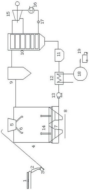
[0017] Embodiment 1: see figure 1 , a sinter vertical cooling device for heat cascade recovery of waste gas full cycle, the device includes a sintering machine 1, a feeding pipe 2, a material truck 3, a vertical cooling furnace 4, a material bin 5, a material distribution pipe 6, and a discharge pipe 7. Belt 8. Gravity dust collector 9. Waste heat boiler 10. Multi-tube dust collector 11. Hot water generator 12. Circulation fan 13. Air distributor 14. Turbine generator set 15. Condenser 16. Water pump 17. Heat storage station 18 and hot water truck 19, the feed bin 5 is arranged on the top of the shaft furnace 4, the distribution pipe 6 is arranged under the feed bin 5, the discharge pipe 7 is arranged at the bottom of the shaft furnace, and the shaft furnace 4 The gravity dust collector 9 and the waste heat boiler 10 are connected to the multi-tube dust collector 11, the hot water generator 12, and the circulating fan 13. 1. The water pump 17 is connected to the waste heat bo...
PUM
Abstract
The invention relates to a sinter vertical cooling device capable of realizing gradient heat recovery and complete waste gas circulation. The device comprises a sintering machine, a discharging pipe,a skip car, a vertical cooling furnace, a stock bin, distributing pipes, discharging pipes, a belt, a gravity dust remover, a waste heat boiler, a multi-pipe dust remover, a hot water generator, a circulating fan, an air distributor, a steam turbine generator unit, a condenser, a water pump, a heat storage station and a hot water car, wherein the stock bin is arranged at the top of the vertical cooling furnace, the distributing pipes are arranged below the stock bin, the discharging pipes are arranged at the bottom of the vertical cooling furnace, the vertical cooling furnace is connected withthe multi-pipe dust remover, the hot water generator and the circulating fan through the gravity dust remover and the waste heat boiler, the heat storage station is connected with the hot water generator, and the steam turbine generator unit is connected with the waste heat boiler through the condenser and the water pump. According to the sinter vertical cooling device, the vertical cooling furnace adopts an optimized structural form, so that efficient heat exchange is achieved, and the sinter cooling requirement is met.
Description
technical field [0001] The invention relates to a cooling device, in particular to a vertical cooling device for sintered ore with cascaded heat recovery and exhaust gas full circulation, and belongs to the technical field of waste heat recovery of sintered ore. Background technique [0002] In the whole process of iron and steel production, the sintering process has high energy consumption and large emission of exhaust gas and dust. The traditional sinter ring cooling process has brought great challenges to the current green manufacturing development and upgrading of the iron and steel industry. The vertical cooling of sintering can significantly reduce the waste gas emission and dust in the sintering production process, improve the effect of energy recovery and utilization, and solve the bottleneck of sintering development. It is the future technology development direction. [0003] In the current relevant literature, the existing sinter vertical cooling technologies all h...
Claims
Application Information
Patent Timeline
Application Date:The date an application was filed.
Publication Date:The date a patent or application was officially published.
First Publication Date:The earliest publication date of a patent with the same application number.
Issue Date:Publication date of the patent grant document.
PCT Entry Date:The Entry date of PCT National Phase.
Estimated Expiry Date:The statutory expiry date of a patent right according to the Patent Law, and it is the longest term of protection that the patent right can achieve without the termination of the patent right due to other reasons(Term extension factor has been taken into account ).
Invalid Date:Actual expiry date is based on effective date or publication date of legal transaction data of invalid patent.