Armored detection integrated photoelectric composite cable

A photoelectric composite cable and armoring technology, which is applied to power cables including optical transmission components, power cables, insulated cables, etc., can solve the problems of high production cost and production risk, low convenience of use, and no realization, and achieve an improvement Ease of use and stability, improved mechanical performance and sensitivity, extended functions and application scenarios

Inactive Publication Date: 2021-03-30
浙江亨通智声科技有限公司
View PDF10 Cites 0 Cited by
  • Summary
  • Abstract
  • Description
  • Claims
  • Application Information

AI Technical Summary

Problems solved by technology

At present, the cable function in the ocean observation system is single. The photoelectric composite submarine optical cable and the detection cable are two separate cables. The unification of communication, detection, and power transmission functions has not been realized. The design has redundancy, and the production cost and production risk are high. Low ease of use
[0004] In addition, the sensing optical unit of the existing detection cable is a tight-buffered optical fiber, or a structure of optical fiber + reinforced aramid fiber + coating layer. This sensing optical unit has a large optical fiber macrobending loss under a small bending radius, and it is impossible to achieve small-pitch winding. package, resulting in low detection sensitivity
In addition, braided aramid fiber reinforcement or braided aramid fiber + coating reinforcement can increase the mechanical strength of the optical fiber, but it is not resistant to compression and wear, and is prone to damage or fiber breakage during the wrapping process, reducing the reliability of the cable.

Method used


Image

  • Armored detection integrated photoelectric composite cable

Examples


Embodiment Construction

[0020] The following will clearly and completely describe the technical solutions in the embodiments of the present invention. Obviously, the described embodiments are only some of the embodiments of the present invention, rather than all the embodiments. Based on the embodiments of the present invention, all other embodiments obtained by persons of ordinary skill in the art without making creative efforts belong to the protection scope of the present invention.

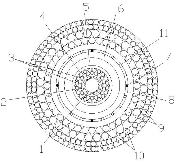
[0021] see figure 1 , the embodiment of the present invention includes:

[0022] Such as figure 1 The armored detection integrated photoelectric composite cable shown includes: a communication power supply functional layer and an acoustic detection functional layer, and uses the communication power supply functional layer to realize signal and power transmission. In this embodiment, the communication power supply functional layer includes a communication optical unit , an inner armor layer 3, a conductive metal tub...


PUM

PropertyMeasurementUnit
Dc resistanceaaaaaaaaaa

Abstract

The invention discloses an armored detection integrated photoelectric composite cable, and the cable comprises a communication power supply function layer which achieves the transmission of signals and power, and comprises a communication optical unit, an inner armored layer, a conductive metal tube, and an inner sheath; an acoustic detection functional layer which is used for detecting acoustic signals in water and comprises a sensitization structure, a sensing light unit and an outer covering acoustic transmission structure, wherein the outer covering acoustic transmission structure is located on the periphery of the sensing light unit and the sensitization structure, makes direct contact with water and transmits underwater acoustic signals to the sensitization structure; the sensitization structure deforms under the action of external sound pressure so as to drive the sensing optical unit to deform, underwater acoustic signals are converted into optical signals, and detection of theunderwater acoustic signals is achieved. Through the above mode, the armored detection integrated photoelectric composite cable achieves the unification of communication, power supply and detection functions, reduces the design redundancy, improves the use convenience and stability, and reduces the production and use cost.

Description

technical field [0001] The invention relates to the technical field of submarine cables, in particular to an armored detection integrated photoelectric composite cable. Background technique [0002] The ocean observation system is a national strategic system that can be applied to underwater target early warning detection, underwater security and underwater acoustic environment monitoring, and is of great significance to national security and environmental monitoring. Conventional ocean observation programs, such as buoy observation, are easily affected by ship activities and difficult to maintain continuous and stable normal work, and the body of buoys will also bring unavoidable obstacles to the passage, berthing and other activities of passing ships. [0003] The cabled online observation system adopts the working method of sitting on the bottom, which is stable and reliable, and can realize long-term, continuous, real-time and online monitoring of marine environmental pa...

Claims


Application Information

Patent Timeline
IPC IPC(8): H01B7/00H01B7/18H01B7/20H01B7/22H01B7/28H01B7/282H01B9/00H01B11/22G01H3/00
CPCH01B7/0045H01B9/005H01B11/22H01B7/18H01B7/22H01B7/207H01B7/282H01B7/28G01H3/00
Inventor 于文慧许人东胥国祥陈金龙李涛康慧灵王悦王畅王方涛刘斌樊玉成
Owner 浙江亨通智声科技有限公司
Why Eureka
Try Eureka