Evaporation-fusion composite laser polishing method capable of realizing peak clipping and then valley filling of metal surface

A metal surface, laser polishing technology, used in laser welding equipment, metal processing equipment, welding equipment, etc., can solve problems affecting metal surface performance, energy input, etc., and achieve the effect of reducing heat input, reducing times, and high polishing efficiency

Pending Publication Date: 2021-04-02
ZHEJIANG UNIV OF TECH
View PDF12 Cites 7 Cited by
  • Summary
  • Abstract
  • Description
  • Claims
  • Application Information

AI Technical Summary

Problems solved by technology

When laser polishing is performed on a surface with a high original roughness value, the increase in the number of continuous laser polishing scans will cause continuous energy input, and duri

Method used


Image

  • Evaporation-fusion composite laser polishing method capable of realizing peak clipping and then valley filling of metal surface
  • Evaporation-fusion composite laser polishing method capable of realizing peak clipping and then valley filling of metal surface
  • Evaporation-fusion composite laser polishing method capable of realizing peak clipping and then valley filling of metal surface

Examples


Embodiment 1

[0030] Embodiment 1 metal surface single continuous laser polishing method

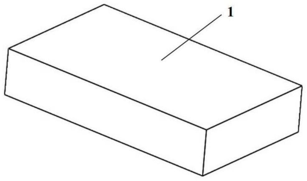
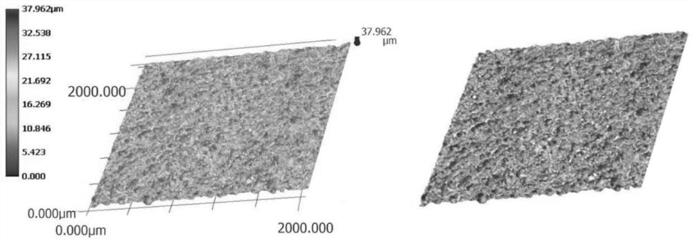
[0031] select as figure 1 The size of the 316L stainless steel block shown is 100mm×60mm×10mm, and its surface 1 is a large roughness surface cut by a model DK77-30 electric discharge CNC wire cutting machine, which is cleaned, dried and pretreated. Surface characterization, characterization results such as figure 2 shown.

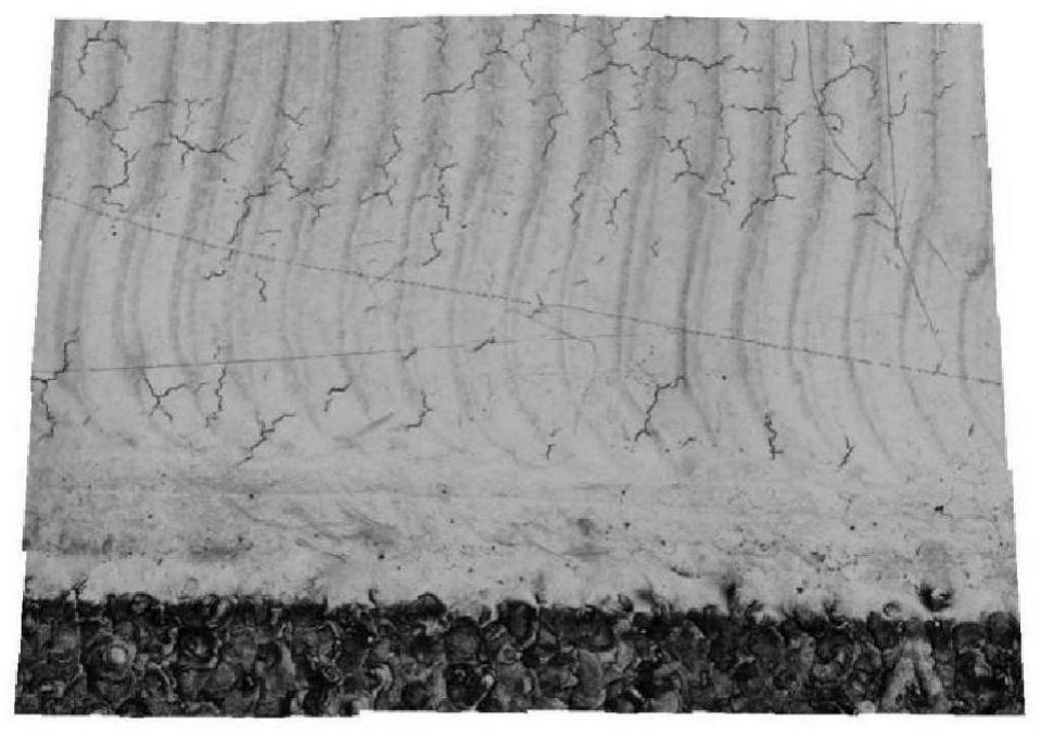
[0032] Place the workpiece in an atmosphere protection box, perform single continuous laser polishing, and set continuous laser parameters: laser wavelength 1064nm, laser power 500W, scanning speed 500mm / s, scanning area 10mm×10mm, scanning line spacing 0.04mm, scanning times 6 times , the scanning and filling method is horizontal scanning from left to right, and vertical stacking from top to bottom. The overlapping rate of vertical stacking is 67%. The surface characterization results are as follows image 3 As shown, there are many microscopic thermal cracks on the surface a...

Embodiment 2

[0033] Example 2 Evaporation-melting composite laser polishing method of first cutting peaks and then filling valleys on the metal surface

[0034] select as figure 1 The size of the 316L stainless steel block shown is 100mm×60mm×10mm, and its surface 1 is a large roughness surface cut by a model DK77-30 electric discharge CNC wire cutting machine, which is cleaned, dried and pretreated. Surface characterization, characterization results such as figure 2 shown.

[0035] Put the workpiece in the atmosphere protection box, perform evaporation-melting composite laser polishing, set the pulse laser parameters: laser wavelength 1064nm, laser power 100W, scanning speed 1000mm / s, repetition frequency 500kHz, pulse width 10ns, scanning area 10mm×10mm , the scanning line spacing is 0.05mm, and the number of scanning is 8 times. The scanning and filling method is horizontal scanning from left to right and vertical stacking from top to bottom. The surface characterization results of ...


PUM


Abstract

The invention provides an evaporation-melting composite laser polishing method capable of realizing peak clipping and then valley filling of a metal surface. According to the method, nanosecond pulselaser is introduced to perform peak clipping treatment on a large-roughness surface, and then composite laser polishing is performed on the large-roughness surface in such a manner that the valley bottom is filled through continuous laser fusion, so that generation of microcracks is prevented; the pulse width of nanosecond laser is extremely short, so that the severe thermal influence cannot be caused by repeated scanning, the surface is bright after action, and the peak of the microscopic surface is cut down; then continuous laser fusion is adopted, the material is fused and flows to fill thevalley bottom, and finally, the flat and bright polished surface without microscopic thermal cracks is obtained. The method is high in polishing efficiency and environmentally friendly.

Description

technical field [0001] The invention relates to an evaporation-melting composite laser polishing method in which peaks are first clipped and then valleys are filled on the metal surface. Background technique [0002] Laser polishing is a new type of material surface treatment technology that has emerged with the development of laser technology. Its basic principle is to use a laser beam with a certain energy density and wavelength to irradiate a specific workpiece to melt or evaporate a thin layer of material on its surface. Get a smooth finish. Because laser polishing only works on the material layer with a thickness of micron, it has higher processing precision than ordinary laser beam processing metal. Since this method does not require any mechanical abrasives and polishing tools, it can polish surfaces with very complex shapes that are difficult or impossible to polish with traditional polishing methods, and it also provides the possibility of automated processing. Po...

Claims


Application Information

Patent Timeline
IPC IPC(8): B23K26/082B23K26/352B23K26/70
CPCB23K26/3576B23K26/082B23K26/702
Inventor 王梁黄锦榜姚建华吴国龙
Owner ZHEJIANG UNIV OF TECH
Why Eureka
Try Eureka