Method and system for determining position of magnetic field detection part of current sensor and sensor

A current sensor and detection component technology, applied in the field of magnetic induction, can solve the problems of large difference in measurement error, measurement of AC current error, large error, etc., achieve no high-frequency hysteresis loss, improve measurement accuracy, and have no magnetic core saturated effect

Pending Publication Date: 2021-04-06
NING BO SINOMAGS ELECTRONICS TECH CO LTD
View PDF0 Cites 7 Cited by
  • Summary
  • Abstract
  • Description
  • Claims
  • Application Information

AI Technical Summary

Problems solved by technology

[0003] However, due to the skin effect of the copper bar (busbar), the sensitivity of the traditional coreless copper bar current sensor changes with the current frequency. The coreless copper bar current sensor can accurately measure the DC current of the copper bar. But there will be a large error when measuring AC current
[0004] Moreover, when the traditional coreless copper bar current sensor optimizes the frequency characteristics, it needs to perform special treatment on the local structure of the copper bar, which requires high processing accuracy, and needs to reduce the part of the copper bar, which will affect the copper bar. flow capacity
[0005] At present, the copper bar current sensor without magnetic core still has a large error when measuring the copper bar current. A large part of the reason is that when the copper bar current sensor is made, the position of the magnetic field detection component in the copper bar current sensor is not correct. Reasonable selection leads to the failure of the copper bar current sensor to meet the optimal standard, so that there is still a large difference in the measurement error

Method used


Image

  • Method and system for determining position of magnetic field detection part of current sensor and sensor
  • Method and system for determining position of magnetic field detection part of current sensor and sensor
  • Method and system for determining position of magnetic field detection part of current sensor and sensor

Examples


Embodiment 1

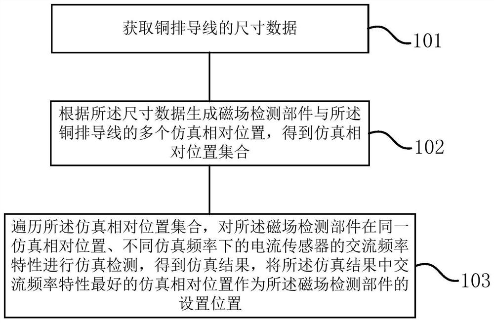
[0052] This embodiment provides a method for determining the position of a magnetic field detection component of a current sensor, figure 1 It is a flow chart illustrating that according to some embodiments of the present invention, the simulation relative position with the best AC frequency characteristic is obtained by performing simulation detection on the copper busbar conductors. Although the processes described below include operations in a particular order, it should be clearly understood that these processes may also include more or fewer operations, which may be performed sequentially or in parallel (e.g., using parallel processors) or multi-threaded environment).

[0053] This embodiment provides a method for determining the position of the magnetic field detection component of the current sensor, which is used to determine the simulated relative position with the best AC frequency characteristics of the copper bar conductor, such as figure 1 shown, including the fo...

Embodiment 2

[0091] The traditional copper bar current sensor with a magnetic core is bulky and expensive, and the magnetic core is easily saturated when measuring a large current, so it is not suitable for use in a compact power electronic system.

[0092] Therefore, the present embodiment provides an AC coreless current sensor 500, such as Figure 9 As shown, it includes a first magnetic field detection component 501, a second magnetic field detection component 502, a third magnetic field detection component 503 and a fourth magnetic field detection component 504, the first magnetic field detection component 501 and the second magnetic field detection component 502 are located on the copper bar wire 506, the third magnetic field detection part 503 and the fourth magnetic field detection part 504 are located on the other side of the copper bar wire 506, the first magnetic field detection part 501, the second magnetic field detection part 502, the third magnetic field detection part 503 and...

Embodiment 3

[0098] This embodiment provides a detection system for an AC coreless current sensor, including a simulation device (not shown), which is used to determine the position of the magnetic field detection component by using the method for determining the position of the magnetic field detection component of the current sensor described in Embodiment 1. The setting position, that is, the position where the magnetic field detection component is set in the current sensor is least affected by the skin effect. For details, please refer to the relevant description of the above-mentioned method embodiment 1, which will not be repeated here.

[0099] Such as Figure 9 As shown, a current sensor 500 is also included, including a first magnetic field detection component 501, a second magnetic field detection component 502, a third magnetic field detection component 503 and a fourth magnetic field detection component 504, which are arranged around the copper bar conductor 506 based on the se...


PUM

PropertyMeasurementUnit
distanceaaaaaaaaaa
distanceaaaaaaaaaa
current densityaaaaaaaaaa

Abstract

The invention provides a method and system for determining the position of a magnetic field detection part of a current sensor, and the sensor. The method comprises the following steps: obtaining the size data of a copper bar wire; generating a plurality of simulation relative positions of the magnetic field detection part and the copper bar wire according to the size data to obtain a simulation relative position set; and traversing the simulation relative position set, carrying out simulation detection on the alternating-current frequency characteristics of the current sensor of the magnetic field detection component at the same simulation relative position and different simulation frequencies to obtain a simulation result, and taking the simulation relative position with the best alternating-current frequency characteristic in the simulation result as a setting position of the magnetic field detection component. The simulation relative position with the best alternating current frequency characteristic in the simulation result is used as the setting position of the magnetic field detection part in the current sensor, so that the influence of the skin effect on the sensitivity of the current sensor can be reduced by the obtained current sensor; and therefore, the error of the copper bar current sensor during measurement of the copper bar wire with the alternating current is reduced.

Description

technical field [0001] The invention relates to the field of magnetic induction, in particular to a method, system and sensor for determining the position of a magnetic field detection component of a current sensor. Background technique [0002] In recent years, power electronic systems such as new energy vehicles, photovoltaic power stations, communication base stations, and energy storage are gradually developing towards modularization, integration, high power density, and small size. Due to its small size and strong flow capacity, copper bars can meet the needs of the development of power electronic systems. [0003] However, due to the skin effect of the copper bar (busbar), the sensitivity of the traditional coreless copper bar current sensor changes with the current frequency. The copper bar current sensor without a magnetic core can accurately measure the DC current of the copper bar. But there will be a large error when measuring AC current. [0004] Moreover, when...

Claims


Application Information

Patent Timeline
Patent Type & Authority Applications(China)
IPC IPC(8): G01R19/00G01R15/20
CPCG01R15/205G01R19/0092
Inventor 徐晓鹏谈侃白建民姚锡刚高超
Owner NING BO SINOMAGS ELECTRONICS TECH CO LTD
Why Eureka
Try Eureka