Composite foundation structure of offshore wind power single pile, supporting disc and small suction barrels and construction method of composite foundation structure

An offshore wind power and composite foundation technology, applied in infrastructure engineering, protective devices, buildings, etc., can solve problems such as limited anti-wind and wave erosion and anti-overturning capabilities, improve horizontal bearing capacity and anti-overturning ability, and reduce engineering costs , High construction efficiency

Pending Publication Date: 2021-04-09
CHINA THREE GORGES CORPORATION +1
View PDF9 Cites 1 Cited by
  • Summary
  • Abstract
  • Description
  • Claims
  • Application Information

AI Technical Summary

Problems solved by technology

In addition, CN 209636843 U discloses a three-barrel jacket-large-diameter single-pile composite foundation for offshore wind turbines, but its anti-wind and wave erosion and anti-overturning capabilities are limited

Method used


Image

  • Composite foundation structure of offshore wind power single pile, supporting disc and small suction barrels and construction method of composite foundation structure
  • Composite foundation structure of offshore wind power single pile, supporting disc and small suction barrels and construction method of composite foundation structure
  • Composite foundation structure of offshore wind power single pile, supporting disc and small suction barrels and construction method of composite foundation structure

Examples


Embodiment 1

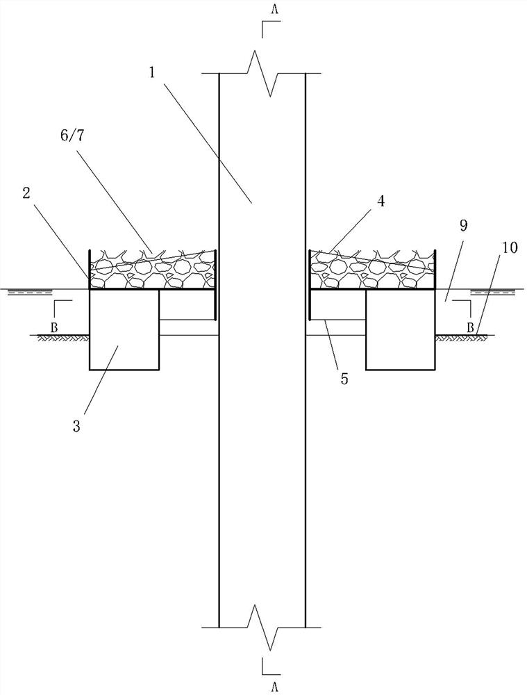
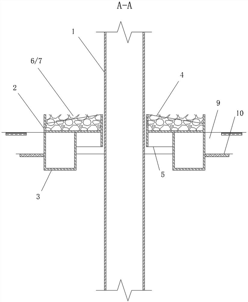
[0041] see Figure 1-6 , a composite foundation structure of an offshore wind power single pile, a support plate and a small suction barrel, which includes a steel pipe pile 1, a support plate 2 and a small suction barrel 3; the outer wall of the steel pipe pile 1 is connected to the inner wall of the support plate 2 The support plate 2 and the steel pipe pile 1 are concentrically arranged; the support plate 2 is provided with a first rib 4 inside; the support plate 2 is provided with a small suction bucket 3 and a second rib 5 at the bottom. There are two possible construction methods as follows:

[0042] One is to first drive the steel pipe pile 1 to the target depth; then insert the supporting plate 2 and the overall structure of the small suction bucket 3 from the top of the steel pipe pile 1, and make the bottom of the small suction bucket 3 approach or touch the bottom of the seabed through its own weight. The surface of the silt layer 9; through the suction device 8, t...

Embodiment 2

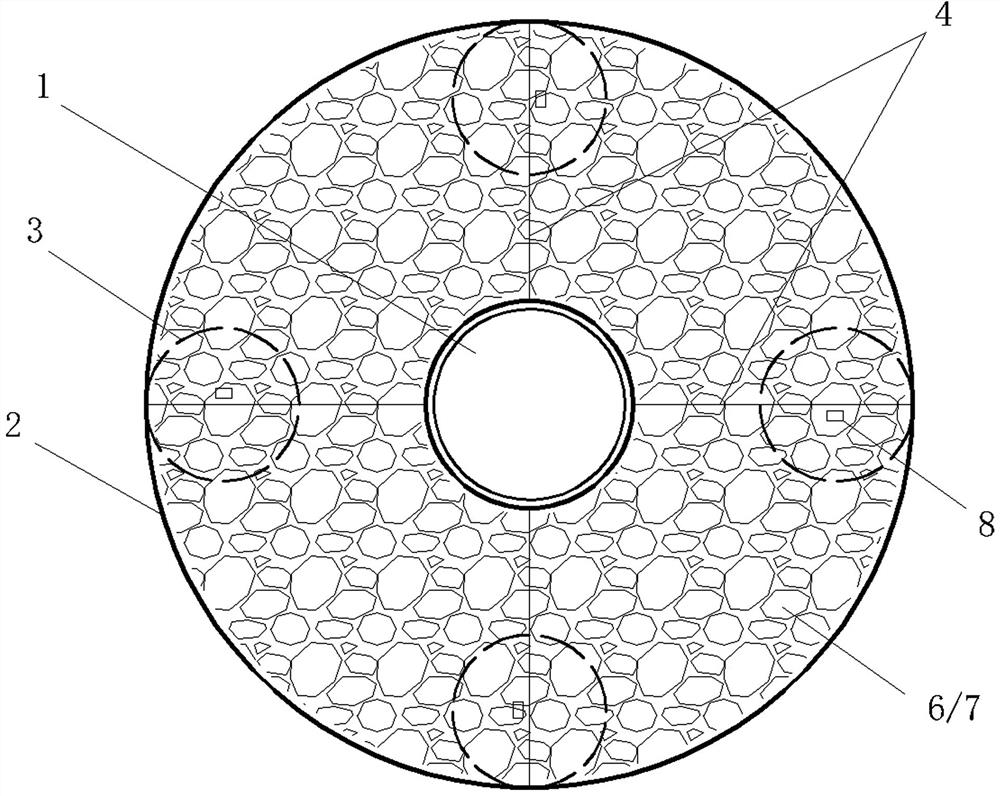
[0049] see Figure 1-6 , In this embodiment, a first rib plate 4 is manufactured inside the support plate 2, and the rib plate may adopt a trapezoidal or rectangular shape. The two parallel sides of the first rib 4 are respectively fixedly connected with the inner wall and the outer wall of the supporting plate 2 ; there are a plurality of the first ribs 4 , and they are evenly distributed inside the supporting plate 2 . Adopting the first rib 4, on the one hand, it increases the overall strength of the supporting plate 2; on the other hand, a plurality of fan-shaped areas are formed inside the supporting plate 2, which provides ample space for the arrangement of suction devices, rockfill dumping or concrete pouring. space.

[0050]Further, the diameter of the support plate 2 is 25-40m. The purpose is to obtain the best pile foundation support effect.

[0051] Further, the number of first ribs 4 inside the support plate is 3-8. The purpose is to obtain the best structural ...

Embodiment 3

[0053] see Figure 1-6 , in this embodiment, a small suction bucket 3 and a second rib 5 are manufactured at the bottom of the support plate 2 . The top of the small suction bucket 3 is connected to the bottom of the support plate 2; The second rib 5 can be trapezoidal or rectangular, and the two parallel sides of the second rib 5 are fixedly connected with the inner wall of the support plate 2 and the outer wall of the small suction bucket 3 respectively, which strengthens the composite foundation.

[0054] Further, the diameter of the small suction barrel 3 is 6-10m. The purpose is to obtain the best pile foundation support effect.

[0055] Further, the number of the second ribs 5 at the bottom of the support plate and the number of the small suction barrels 3 are kept the same, ranging from 3 to 6. The purpose is to obtain the best structural reinforcement effect and pile foundation support effect.


PUM

PropertyMeasurementUnit
Diameteraaaaaaaaaa

Abstract

The invention discloses a composite foundation structure of an offshore wind power single pile, a supporting disc and small suction barrels and a construction method of the composite foundation structure. The composite foundation structure comprises the steel pipe pile, the supporting disc and the small suction barrels, wherein the steel pipe pile is fixedly installed at the position of a center hole of the supporting disc, and the steel pipe pile and the supporting disc are kept concentrically arranged; a first rib plate is arranged in the supporting disc; the small suction barrels are evenly distributed and fixed to the bottom end of the supporting disc; second rib plates are arranged between the small suction barrels and the supporting disc; and the supporting disc is filled with riprap or concrete. Through the supporting disc and the small suction barrels, a composite foundation adapts to the seabed geological environment with a sludge covering layer and has higher vertical bearing capacity and lateral bearing capacity. The supporting disc is riprap or concrete is poured, the cover weight is increased, and therefore soil is enhanced, the anti-overturning capacity of the foundation is improved, and scouring of waves to the seabed soil is stopped.

Description

technical field [0001] The invention relates to an underwater foundation structure of offshore wind power, in particular to a composite foundation structure of a single pile of offshore wind power, a support plate and a small suction bucket and a construction method thereof, belonging to the fields of geotechnical engineering and marine engineering. Background technique [0002] Wind energy is a clean and renewable energy source. Offshore wind energy resources have the characteristics of high and stable wind speed, abundant energy storage, wide distribution, high power generation output and long service life, and have broad development prospects. At present, the construction of offshore wind power projects is in a period of rapid development. As a convenient basic structure, single piles are widely recognized by design and construction units. However, when the thickness of the underwater covering layer is shallow or the upper seabed foundation is soft clay, in order to ensu...

Claims


Application Information

Patent Timeline
IPC IPC(8): E02D27/42E02D27/52E02D27/50E02D31/00
CPCE02D27/425E02D27/50E02D27/525E02D31/00
Inventor 吴敬凯张丙印于玉贞刘建平尹文杰王翔南袁玮鸿郝青硕方楠
Owner CHINA THREE GORGES CORPORATION
Why Eureka
Try Eureka