
Metal part of processing chamber and method of forming layer of metal part of processing chamber

A technology for metal parts and processing chambers, applied in metal material coating process, superimposed layer plating, coating and other directions, can solve the problem of damage to the substrate, cannot fully solve the problem of ensuring the thickness of the surface treatment layer, and reducing the production yield.

Pending Publication Date: 2021-04-16
POINT ENG
View PDF1 Cites 0 Cited by
  • Summary
  • Abstract
  • Description
  • Claims
  • Application Information

AI Technical Summary

Problems solved by technology

This phenomenon is called foreign matter outgassing (Out-gassing) phenomenon, and it is the main cause of poor treatment of the processing chamber, reduction of production yield, and shortening of the maintenance and repair cycle of the processing chamber
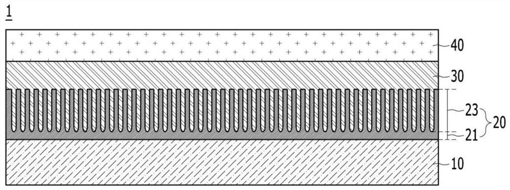
[0010] In order to prevent the outgassing phenomenon as described above, in the case where the surface treatment of the internal metal parts for the processing chamber is performed by forming only the non-porous barrier layer, the non-porous barrier layer is subject to internal stress due to its too thin thickness. The influence of change or thermal expansion causes cracks (Crack) in the anodized film or the problem that the anodized film is peeled off
In addition, a thin anodized film comprising only a non-porous barrier layer has a short life, easily exposes the aluminum or aluminum alloy substrate, and generates a plasma arc discharge ( Plasma Arcing), resulting in the problem of partially melting or damaging the surface of the substrate
[0011] As mentioned above, when the surface treatment layer (hereinafter referred to as "thin film layer") used for the internal metal parts of the processing chamber is formed only from the conventional anodized film, it is not possible to fully solve the problem of ensuring the thickness of the surface treatment layer and preventing outgassing

Method used


Image

  • Metal part of processing chamber and method of forming layer of metal part of processing chamber
  • Metal part of processing chamber and method of forming layer of metal part of processing chamber
  • Metal part of processing chamber and method of forming layer of metal part of processing chamber

Examples


Embodiment Construction

[0087] Hereinafter, preferred embodiments of the present invention will be described in detail with reference to the accompanying drawings. The advantages and features of the present invention and methods for achieving them will become apparent with reference to the accompanying drawings and the embodiments to be described in detail below. However, the present invention is not limited to the embodiments described here, and may also be embodied in forms different from each other. Rather, the embodiments described herein are provided so that the disclosed content may become thorough and complete and fully convey the idea of ​​the present invention to those skilled in the art, and the present invention is only defined by the scope of the claims . Throughout the specification, the same reference signs refer to the same constituent elements.

[0088] The terms used in this specification are for describing the embodiments and are not intended to limit the present invention. In th...


PUM

PropertyMeasurementUnit
thicknessaaaaaaaaaa
thicknessaaaaaaaaaa
thicknessaaaaaaaaaa

Abstract

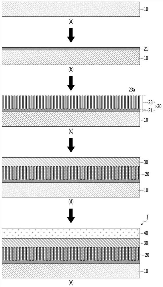
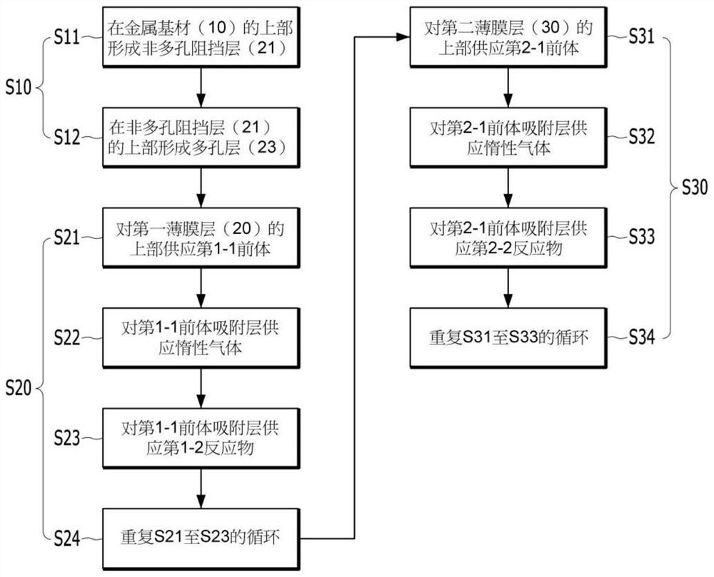
The invention relates to an internal metal part for a processing chamber and a method for forming a thin film layer of the internal metal part for the processing chamber, and more particularly, to an internal metal part for a processing chamber and a method for forming a thin film layer of an internal metal part for a processing chamber, the part is arranged in a processing chamber used for display or semiconductor manufacturing processing or forms a part of the processing chamber, it is possible to easily ensure a thick thickness of a thin film layer of an internal metal part for the processing chamber and to achieve a life extension by preventing cracks of the internal metal part of the processing chamber, while preventing a gas escape phenomenon caused by voids.

Description

technical field [0001] The present invention relates to an inner metal part for a processing chamber and a method for forming a thin film layer for an inner metal part of a processing chamber, in particular to a processing chamber provided in or constituting a processing chamber for display or semiconductor manufacturing processing A part of an internal metal part for a processing chamber and a thin film layer forming method for an internal metal part of a processing chamber. Background technique [0002] Chemical vapor deposition processing equipment (chemical vapor deposition (Chemical Vapore Deposition, CVD) equipment), physical vapor deposition processing equipment (physical vapor deposition (Physical Vapore Deposition, PVD) equipment), dry etching processing equipment (dry etching (Dry Etching) ) device) etc. (hereinafter referred to as "processing chamber") uses reaction gas, etching gas or cleaning gas (hereinafter referred to as "processing gas") inside the processin...

Claims


Application Information

Patent Timeline
Patent Type & Authority Applications(China)
IPC IPC(8): C23C28/04C25D11/04C25D11/18C23C16/455C23C16/40C23C16/34C23C16/32
CPCC23C16/4404C23C16/045C23C16/45525C23C16/40C25D11/24C23C28/048C25D11/02C25D11/18C25D11/12C25D11/045
Inventor 安范模
Owner POINT ENG
Learn More