Rapid blending equipment for mortar production

A fast and equipment technology, applied in clay preparation devices, raw material supply devices for sale, mixing operation control devices, etc., can solve the problems of lack of raw material pretreatment function, sedimentation in the lower layer, and decreased mixing efficiency.

Inactive Publication Date: 2021-04-23
安徽瞬达信息科技有限公司
View PDF8 Cites 1 Cited by
  • Summary
  • Abstract
  • Description
  • Claims
  • Application Information

AI Technical Summary

Problems solved by technology

[0009] The existing mortar preparation and blending devices lack targeted equipment, and most of them are simple stirring devices, which mix raw materials and water for stirring, and there are some problems:
[0010] Due to the difference in the density of raw materials and water, some are easy to float on the upper layer, and some are settled on the lower layer. However, most of the existing mixing equipment adopts fixed mixing blades, which are prone to dead spots in the mixing, which will cause uneven mixing of raw materials. ; and the mortar raw materials are prone to agglomeration, and the existing device also lacks the pretreatment function of the raw materials, so that the agglomerated raw materials and water are directly mixed, which easily leads to a decline in mixing efficiency

Method used


Image

  • Rapid blending equipment for mortar production
  • Rapid blending equipment for mortar production
  • Rapid blending equipment for mortar production

Examples


Embodiment 1

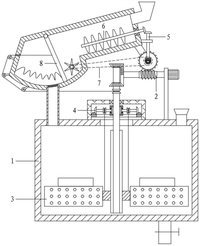
[0060] Referring to the accompanying drawings, a rapid deployment equipment for mortar production includes a frame assembly 1, a driving assembly 2, a stirring assembly 3, a lifting assembly 4, a transmission assembly 5 and a crushing assembly 6;

[0061] The frame assembly 1 includes a mixing tank 101, a slurry discharge pipe 102, a liquid feeding port 103, a feeding pipe 104, a material receiving cavity 105, a crushing cavity 106 and a feeding hopper 107; the crushing cavity 106 is arranged low on the left and high on the right. The left end of the hopper 107 is connected with a material receiving cavity 105; the mixing tank 101 is located below the material receiving cavity 105, and the bottom end of the material receiving cavity 105 is connected to the left end of the top of the mixing tank 101 through the feeding pipe 104; the right end of the mixing tank 101 is provided with a liquid filling port 103 , the bottom is connected with a slurry pipe 102, and the slurry pipe 10...

Embodiment 2

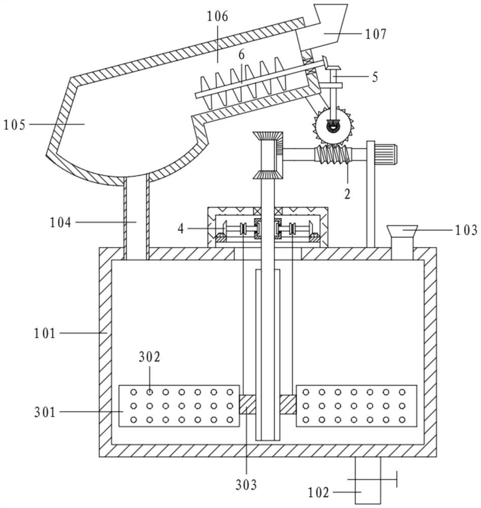
[0064] Referring to the accompanying drawings, a rapid deployment equipment for mortar production includes a frame assembly 1, a driving assembly 2, a stirring assembly 3, a lifting assembly 4, a transmission assembly 5 and a crushing assembly 6;

[0065] The frame assembly 1 includes a mixing tank 101, a slurry discharge pipe 102, a liquid feeding port 103, a feeding pipe 104, a material receiving cavity 105, a crushing cavity 106 and a feeding hopper 107; the crushing cavity 106 is arranged low on the left and high on the right. The left end of the hopper 107 is connected with a material receiving cavity 105; the mixing tank 101 is located below the material receiving cavity 105, and the bottom end of the material receiving cavity 105 is connected to the left end of the top of the mixing tank 101 through the feeding pipe 104; the right end of the mixing tank 101 is provided with a liquid filling port 103 , the bottom is connected with a slurry pipe 102, and the slurry pipe 10...

Embodiment 3

[0085] On the basis of Example 2,

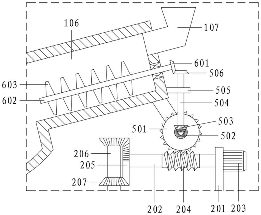
[0086]It also includes a pulverizing assembly 7; the pulverizing assembly 7 is located on the right side of the feeding tube 104, and includes the No. 1 transmission wheel 701, the transmission belt 702, the No. 2 transmission wheel 703, the installation shaft 704 and the crushing knife 705;

[0087] The installation shaft 704 is installed in the material receiving chamber 105, and the front and rear ends are rotatably connected to the inner wall of the material receiving chamber 105; the installation shaft 704 is evenly installed with a crushing knife 705; The No. 1 transmission wheel 701 is connected, and the No. 1 transmission wheel 701 and the No. 2 transmission wheel 703 are connected through a transmission belt 702.

[0088] Specifically, when the worm wheel 501 rotates, it also drives its coaxial No. 1 transmission wheel 701 to rotate; It rotates and produces a pulverizing effect; the mortar raw material falling into the receiving ca...


PUM


Abstract

The invention relates to the technical field of mortar preparation treatment, in particular to rapid blending equipment for mortar production. According to the equipment, a servo motor is adopted to drive a first rotating shaft to rotate, a transmission assembly drives a crushing assembly to work, and a crushing knife generates a crushing effect in a crushing cavity so as to carry out particle refinement on mortar raw materials, and subsequent pulping is facilitated; the first rotating shaft drives a second rotating shaft to rotate forwards and backwards in a reciprocating mode through a driving assembly, and a spline shaft below the second rotating shaft rotates along with the second rotating shaft and drives a sliding sleeve to drive stirring blades to circumferentially rotate to achieve a stirring effect; the second rotating shaft also circumferentially rotates along with the first rotating shaft, and a second driven bevel gear at an outer end is matched with a gear ring at a fixed position, and the second driven bevel gear drives the second rotating shaft to rotate, so that a reel performs automatic and periodic take-up and pay-off operations; and by matching with the dead weight of the stirring assembly, the stirring assembly moves up and down along the spline shaft, so that the stirring action area of the stirring blades is changed and the stirring dead angle is eliminated.

Description

technical field [0001] The invention relates to the technical field of mortar preparation and treatment, and relates to a rapid deployment equipment for mortar production. Background technique [0002] Construction engineering refers to the engineering entity formed through the construction of various housing buildings and their ancillary facilities and the installation of their supporting lines, pipelines, and equipment. Among them, "house construction" refers to projects with roofs, beams, columns, walls, foundations, and the ability to form internal spaces to meet the needs of people's production, living, learning, and public activities. [0003] The small artificial blocks used in construction are divided into sintered bricks (mainly clay bricks) and non-sintered bricks (lime sand bricks, fly ash bricks, etc.), commonly known as bricks. Clay bricks are made of clay (including shale, coal gangue and other powders) as the main raw material, which is processed, shaped, dri...

Claims


Application Information

Patent Timeline
Patent Type & Authority Applications(China)
IPC IPC(8): B28C5/48B28C5/16B28C5/08B28C7/00B28C7/06B02C21/00B02C18/06B02C18/24B02C18/14
CPCB02C18/06B02C18/145B02C18/24B02C21/00B28C5/0831B28C5/16B28C5/485B28C7/0007B28C7/06
Inventor 王中燕
Owner 安徽瞬达信息科技有限公司
Why Eureka
Try Eureka