
Inductive energy storage type temperature sensor

A temperature sensor and energy storage technology, applied in thermometers, thermometer applications, instruments, etc., can solve the problem of inability to quickly locate the fault location, high labor intensity of electric workers, and failure to achieve the degree of deterioration and operating status of key parts of electrical equipment Real-time monitoring and other issues

Pending Publication Date: 2021-04-27
北京迈驰电气技术有限公司
View PDF0 Cites 0 Cited by
  • Summary
  • Abstract
  • Description
  • Claims
  • Application Information

AI Technical Summary

Problems solved by technology

[0002] In China, most of the medium and low-voltage distribution networks adopt the neutral point ungrounded or small resistance grounding system. When a single-phase ground fault occurs, the cable insulation has actually broken down and generated heat. However, due to the large grounding resistance and small grounding current, distribution The network background monitoring system and relay protection device cannot be removed. The power supply department will not know the actual situation of the equipment until the fault develops into a serious situation of burning, smoking or even explosion.
[0003] The temperature measurement of the original equipment is only a means to monitor the insulation aging and operating status of the power distribution equipment itself. Due to the lack of detection of the core temperature and ambient temperature and humidity, it is impossible to quickly locate the fault location when an accident occurs.
[0004] The wiring of high-voltage cabinets and station areas is complicated. When a power failure occurs, the labor force of the electric staff is high, the work efficiency is low, and the maintenance cost is too high. Real-time monitoring of the deterioration degree and operating status of key parts of electrical equipment cannot be achieved. It is impossible to intelligently manage the urban distribution network

Method used


Image

  • Inductive energy storage type temperature sensor
  • Inductive energy storage type temperature sensor
  • Inductive energy storage type temperature sensor

Examples


Embodiment 1

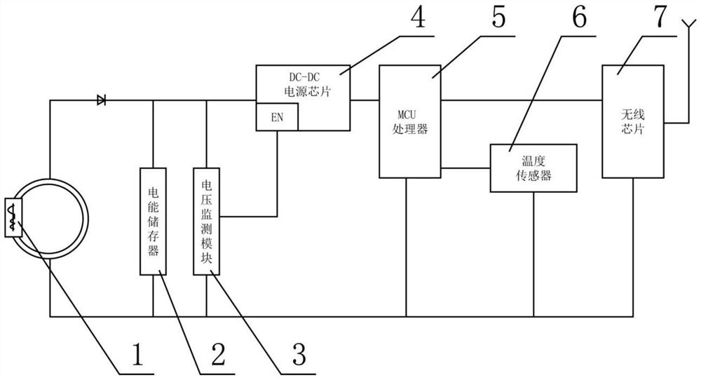
[0027] The embodiment of the present invention discloses an inductive energy storage temperature sensor, such as figure 1 , 4 , 5, including energy sensing module 1, electric energy storage 2, voltage monitoring module 3, DC-DC power supply chip 4, MCU processor 5, temperature sensor 6 and wireless chip 7, the energy sensing module 1 through the diode and The electric energy storage 2 is connected, the electric energy storage 2 adopts a capacitor, the electric energy storage 2 is connected to the voltage monitoring module 3, and the voltage monitoring module 3 is connected to the DC-DC power supply chip 4, so The DC-DC power supply chip 4 supplies power to the MCU processor 5, the temperature sensor 6 and the wireless chip 7, and the MCU processor 5 is connected to the temperature sensor 6 and the wireless chip 7. The input voltage of the DC-DC power supply chip 4 is 4.5V, and the output voltage is 3.3V. The MCU processor 5 adopts a COTREX-MO core CPU. The temperature senso...

Embodiment 2

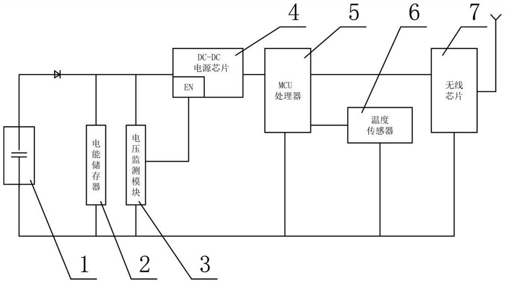
[0031] The embodiment of the present invention discloses an inductive energy storage temperature sensor, such as figure 2 As shown, it includes an energy sensing module 1, an electric energy storage 2, a voltage monitoring module 3, a DC-DC power supply chip 4, an MCU processor 5, a temperature sensor 6 and a wireless chip 7, and the energy sensing module 1 communicates with the The electric energy storage 2 is connected, and the electric energy storage 2 adopts a capacitor, and the electric energy storage 2 is connected with the voltage monitoring module 3, and the voltage monitoring module 3 is connected with the DC-DC power supply chip 4, and the DC - The DC power supply chip 4 supplies power to the MCU processor 5 , the temperature sensor 6 and the wireless chip 7 , and the MCU processor 5 is connected to the temperature sensor 6 and the wireless chip 7 .

[0032] The energy sensing module 1 in this embodiment is a voltage sensing module. The sensor is placed in the equi...

Embodiment 3

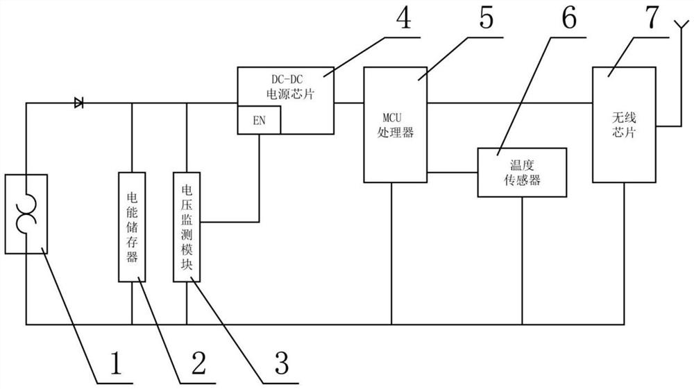
[0034] The embodiment of the present invention discloses an inductive energy storage temperature sensor, such as image 3 As shown, it includes an energy sensing module 1, an electric energy storage 2, a voltage monitoring module 3, a DC-DC power supply chip 4, an MCU processor 5, a temperature sensor 6 and a wireless chip 7, and the energy sensing module 1 communicates with the The electric energy storage 2 is connected, and the electric energy storage 2 adopts a capacitor, and the electric energy storage 2 is connected with the voltage monitoring module 3, and the voltage monitoring module 3 is connected with the DC-DC power supply chip 4, and the DC - The DC power supply chip 4 supplies power to the MCU processor 5 , the temperature sensor 6 and the wireless chip 7 , and the MCU processor 5 is connected to the temperature sensor 6 and the wireless chip 7 .

[0035] The energy sensing module 1 in this embodiment is a temperature difference sensing module. The sensor is plac...


PUM


Abstract

The invention discloses an induction energy storage type temperature sensor, which comprises an energy induction module, an electric energy storage device, a voltage monitoring module, a DC-DC power supply chip, an MCU processor, a temperature sensor and a wireless chip, and is characterized in that the energy induction module is connected with the electric energy storage device through a diode,the electric energy storage device is connected with the voltage monitoring module, the voltage monitoring module is connected with the DC-DC power supply chip, the DC-DC power supply chip supplies power to the MCU processor, the temperature sensor and the wireless chip, and the MCU processor is connected with the temperature sensor and the wireless chip. According to the invention, different types of energy induction modules are used to convert a variable magnetic field emitted by power distribution network equipment into a voltage, or convert a temperature difference between a cable head, a cable core and other components and an ambient temperature into a voltage to supply power to the temperature sensor.

Description

technical field [0001] The invention belongs to the technical field of temperature sensors, in particular to an inductive energy storage type temperature sensor. Background technique [0002] In China, most of the medium and low-voltage distribution networks adopt the neutral point ungrounded or small resistance grounding system. When a single-phase ground fault occurs, the cable insulation has actually broken down and generated heat. However, due to the large grounding resistance and small grounding current, distribution The network background monitoring system and relay protection device cannot be removed. The power supply department cannot know the actual situation of the equipment until the fault develops into a serious situation of burning, smoking or even explosion. [0003] The temperature measurement of the original equipment is only a means to monitor the insulation aging and operating status of the power distribution equipment itself. Due to the lack of detection o...

Claims


Application Information

Patent Timeline
IPC IPC(8): G01K13/00G01R19/00H02J50/10H02J7/34
CPCG01K13/00G01R19/00H02J7/34H02J50/10
Inventor 邱建华白江涛苏宁王健高强赵红茹李芳芳杨希哲李绪东赵永尚云峰郭栋茂谭寿岩
Owner 北京迈驰电气技术有限公司
Learn More