A kind of preparation method of composite core for optical fiber insulator

A composite core and insulator technology, applied in the direction of insulators, optics, light guides, etc., can solve problems such as insulation sealing failure, optical fiber brittleness, and optical fiber cladding peeling off, and achieve the effect of improving practicability

Active Publication Date: 2022-05-17
西安高强绝缘电气有限责任公司
View PDF6 Cites 0 Cited by
  • Summary
  • Abstract
  • Description
  • Claims
  • Application Information

AI Technical Summary

Problems solved by technology

The optical fiber composite insulators made by these two methods have common disadvantages: there is an insulating seal between the inner cavity of the insulating tube or the slotted part of the insulating rod and the surface of the optical fiber. The difference in thermal expansion coefficient between the rod, potting or filling material, and fiber material will cause the insulation seal to fail; stress will be formed in the insulator body, resulting in increased fiber loss; during the process of fiber implantation and potting, it will easily cause the fiber coating to peel off. brittle fracture
The above situations will reduce the qualified rate of making optical fiber insulators

Method used


Image

  • A kind of preparation method of composite core for optical fiber insulator
  • A kind of preparation method of composite core for optical fiber insulator
  • A kind of preparation method of composite core for optical fiber insulator

Examples


Embodiment 1

[0034] This embodiment includes the following steps:

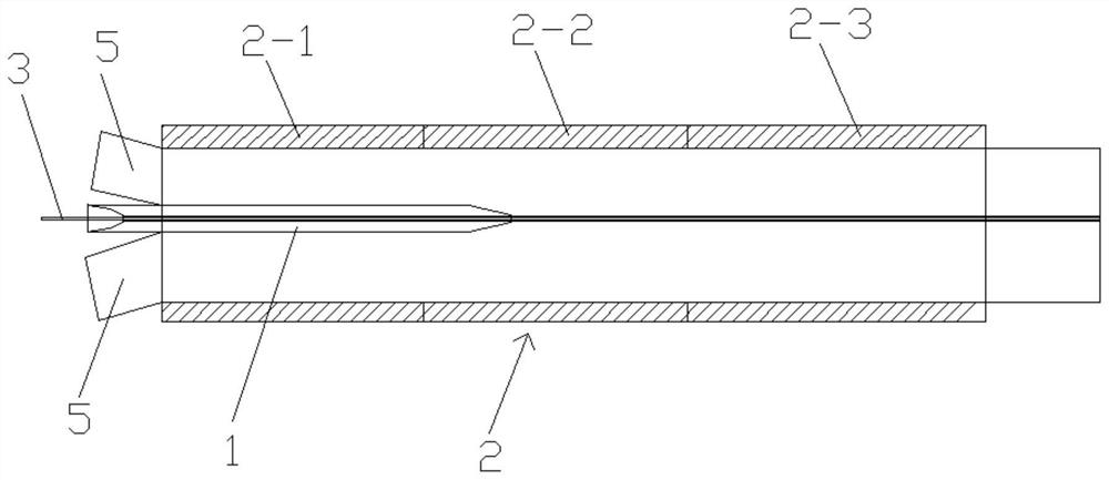
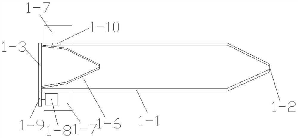
[0035] Step 1. Fix the optical fiber isolation and protection tooling 1 in the pultrusion core mold 2 through the mounting frame 1-7 to obtain a processing device; the length of the pultrusion core mold 2 is 900 mm, and the inner diameter is 50 mm; the optical fiber isolation The length of the protective tooling 1 is 2 / 3 of the length of the pultrusion core mold 2, the diameter of the outlet hole 1-2 is 3mm; the temperature of the preheating zone 2-1 is 90°C-95°C, the The temperature of the forming zone 2-2 is 120°C-127°C, the temperature of the curing zone 2-3 is 155°C-157°C; 2 The distance from the right end face is 1 / 2 of the length of the pultrusion core die 2;

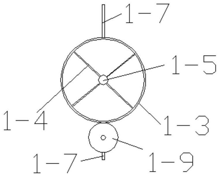
[0036] Step 2: Insert the optical fiber 3 through the optical fiber inlet hole 1-5 in the processing device obtained in step 1 and pass through the outlet hole 1-2 and then pass through the pultrusion core mold 2, and then remove the optical fiber protective ...

Embodiment 2

[0040] This embodiment includes the following steps:

[0041] Step 1. Fix the optical fiber isolation and protection tooling 1 in the pultrusion core mold 2 through the mounting frame 1-7 to obtain a processing device; the length of the pultrusion core mold 2 is 900 mm, and the inner diameter is 35 mm; the optical fiber isolation The length of the protective tooling 1 is 3 / 4 of the length of the pultrusion core mold 2, and the diameter of the outlet hole 1-2 is 5mm; the pultrusion core mold 2 is the preheating zone 2 from left to right -1. Forming zone 2-2 and curing zone 2-3, the temperature of the preheating zone 2-1 is 95°C-103°C, the temperature of the forming zone 2-2 is 127°C-131°C, the The temperature of the curing zone 2-3 is 157°C-159°C; the optical fiber isolation and protection tooling 1 is inserted from the left side of the pultrusion core mold 2, and the outlet hole 1-2 of the optical fiber isolation and protection tooling 1 is drawn The distance from the right e...

Embodiment 3

[0046] This embodiment includes the following steps:

[0047] Step 1. Fix the optical fiber isolation and protection tooling 1 in the pultruded core mold 2 through the mounting frame 1-7 to obtain a processing device; the length of the pultruded core mold 2 is 1200mm, and the inner diameter is 70mm; the optical fiber isolation The length of the protective tooling 1 is 17 / 24 of the length of the pultrusion core mold 2, and the diameter of the outlet hole 1-2 is 6mm; the pultrusion core mold 2 is the preheating zone 2 from left to right -1. Forming zone 2-2 and curing zone 2-3, the temperature of the preheating zone 2-1 is 103°C-105°C, the temperature of the forming zone 2-2 is 131°C-135°C, the The temperature of the curing zone 2-3 is 159°C-165°C; the optical fiber isolation and protection tooling 1 is inserted from the left side of the pultrusion core mold 2, and the outlet hole 1-2 of the optical fiber isolation and protection tooling 1 is drawn The distance from the right e...


PUM

PropertyMeasurementUnit
lengthaaaaaaaaaa
diameteraaaaaaaaaa
diameteraaaaaaaaaa

Abstract

The invention discloses a method for preparing a composite core body for an optical fiber insulator. The method comprises the following steps: 1. fixing an optical fiber isolation and protection tool in a pultrusion core mold; 2. passing an optical fiber through the fiber isolation and protection tool and pulling Extrude the core mold to wrap the optical fiber protective layer on the optical fiber; 3. Wrap the optical fiber coated with the optical fiber protective layer in the center of the glass fiber, and then lead it out from the pultruded core mold to obtain a composite core. In the present invention, the optical fiber isolation protection tool is fixed in the pultrusion core mold, and then the optical fiber protective layer is wound on the optical fiber, and then the glass fiber impregnated with epoxy resin glue is passed through, and the optical fiber coated with the optical fiber protective layer is It is clamped and fixed in the center of the glass fiber, and the optical fiber is directly implanted synchronously during the pultrusion process of the glass fiber to avoid the occurrence of fiber breakage, fiber coating damage or insulation seal failure, and protect the optical fiber to ensure that the energy of the light wave will not loss, improving the practicability of the composite core.

Description

technical field [0001] The invention belongs to the technical field of optical fiber insulators, and in particular relates to a method for preparing a composite core for optical fiber insulators. Background technique [0002] With the development of the power industry, especially the development of UHV power transmission and transformation, higher requirements are put forward for the test equipment in the power system. Traditional electromagnetic transformers have many defects such as large loss and poor response characteristics of high-frequency signals, and it is difficult to meet the needs of EHV / UHV power systems. The optical current sensor has the advantages of strong anti-electromagnetic interference ability and high safety performance, and can meet the requirements of high voltage, high current, and real-time charged measurement. The all-fiber-optic current sensor uses optical fiber as the channel for information transmission. In order to avoid the signal transmitted...

Claims


Application Information

Patent Timeline
Patent Type & Authority Patents(China)
IPC IPC(8): H01B19/00G02B6/44
CPCH01B19/00G02B6/4479G02B6/4486
Inventor 张宝英
Owner 西安高强绝缘电气有限责任公司
Why Eureka
Try Eureka