Ampoule bottle dispensing system and dispensing method thereof
A dispensing system and ampoules technology, which is applied in medical containers, drug packaging, bottle filling, etc., and can solve the problems of high labor intensity and low dispensing efficiency
- Summary
- Abstract
- Description
- Claims
- Application Information
AI Technical Summary
Problems solved by technology
Method used
Image
Examples
Embodiment 1
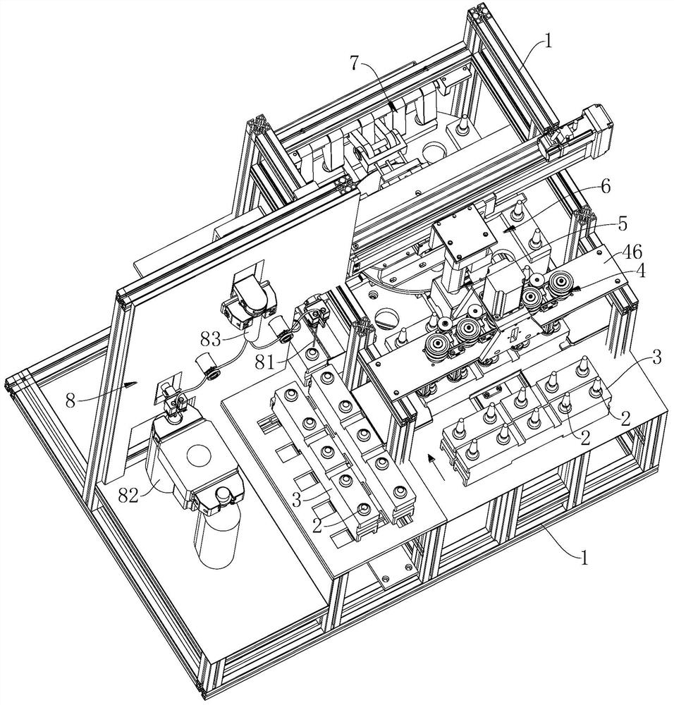
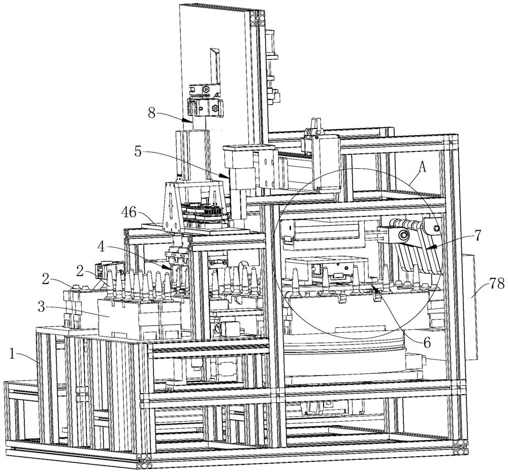
[0069] An ampoule dispensing system such as Figure 1-Figure 20 shown, including
[0070] The storage module 3 is used for assembling and delivering multiple ampoules 2;
[0071] The bottle cutting device 4 is used to simultaneously cut a plurality of ampoules 2 on the storage module 3 with a line;
[0072] The disinfection part 5 is used for spraying disinfectant or alcohol on the cutting part of the ampoule 2, that is, the neck of the bottle;
[0073] The rotating device 6 is used to fix the material storage module 3 and change the dispensing station;
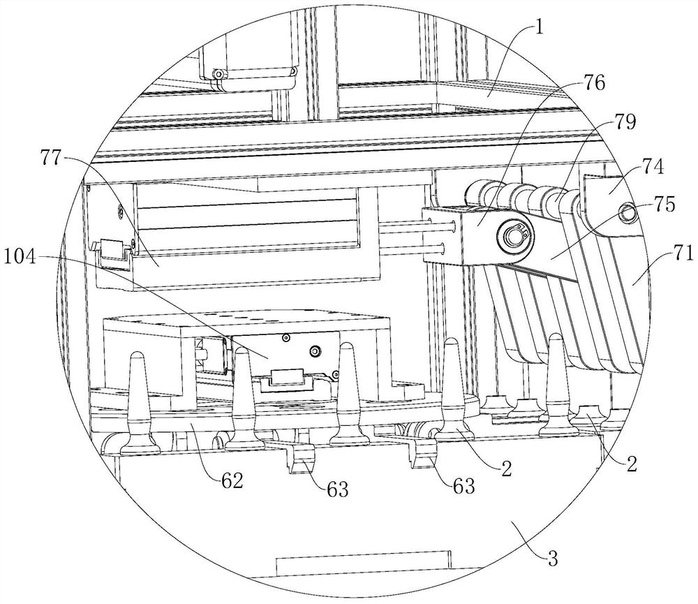
[0074] The bottle breaking device 7 is used to impact and break the bottle head of the ampoule bottle 2;
[0075] The dispensing device 8 is used to suck the medicinal liquid in the ampoule bottle 2 into the infusion bag 82 after the broken bottle.
[0076] The bottle cutting device 4, disinfection unit 5, rotating device 6, bottle breaking device 7 and dispensing device 8 are integrated and installed on the bracket 1. In...
Embodiment 2
[0087] Such as Figure 18-Figure 20, on the basis of Example 1, after the ampoule bottle 2 in the storage module 3 on the rotary device 6 breaks the bottleneck, the rotary device 6 drives the storage module 3 to change to the discharge station, where the station needs The storage module 3 is taken out from the index plate 61 through the discharging mechanism 10 (ie, discharged). Specifically, the discharge mechanism 10 includes a push mechanism and a push mechanism that both perform linear reciprocating motion. on the disk 62 and is used for laterally pushing out the storage module 3 located on the discharge direction of the indexing disk 61. Such as Figure 19 , wherein the pushing mechanism includes a lifting plate 101, the lifting plate 101 is close to the bottom of the material storage module 3, and is driven by the second slide rail assembly 102 for linear reciprocating motion, and the lifting plate 101 is used to push the material storage module 3 to move upward The p...
Embodiment 3
[0090] Based on Example 2, such as Figure 17 , 18 , on both sides of the path where the third slide rail assembly 104 pushes out the storage module 3 laterally, a second guide plate 108 is set, the second guide plate 108 is fixed to the bracket 1, and the second guide plate 108 is used to receive and guide the lifting The lateral movement of the material storage module 3. When the material storage module 3 is released from the stopper 63 and the index plate 61 along the second guide plate 108, in order to further make the suction needle 81 on the installation position of the dispensing system correct the ampoule bottle 2 Chinese medicine liquid after the broken bottle For suction, this embodiment also provides a feeding mechanism to meet the system's dispensing space requirements. A second groove 34 with an open end is further provided on both sides of the material storage module 3 along the length direction, and the opening of the second groove 34 is downward; correspondin...
PUM
 Abstract
Description
Claims
Application Information
 - R&D
- Intellectual Property
- Life Sciences
- Materials
- Tech Scout
- Unparalleled Data Quality
- Higher Quality Content
- 60% Fewer Hallucinations
Browse by: Latest US Patents, China's latest patents, Technical Efficacy Thesaurus, Application Domain, Technology Topic, Popular Technical Reports.
© 2025 PatSnap. All rights reserved.Legal|Privacy policy|Modern Slavery Act Transparency Statement|Sitemap|About US| Contact US: help@patsnap.com


