Power device manufacturing equipment with waste recovery function

A technology for waste recycling and manufacturing equipment, which is applied in the direction of manufacturing tools, welding equipment, auxiliary welding equipment, etc., can solve the problems of reducing work intensity, difficult to control the path of waste materials, and dumping of devices, so as to avoid water pollution, facilitate direct use, and avoid The effect of rising costs

Active Publication Date: 2021-05-07
广州渺钛新材料科技有限公司
View PDF8 Cites 1 Cited by
  • Summary
  • Abstract
  • Description
  • Claims
  • Application Information

AI Technical Summary

Problems solved by technology

[0004] 1. The comparative document CN109955112A discloses an environment-friendly mechanical processing waste collection device, "including a moving chassis, a collection box, a lifting support, a sliding support, a support mechanism, a collection pipe, a collection support, a rotating mechanism, a limit rotating ring, and a rotating support Ⅰ. The rotating bracket Ⅱ and the collection mechanism can use the suction generated by the suction pump set on the moving chassis to make the collection pipe generate suction to absorb and collect the iron filings in machining, and the suction can collect the machining iron filings in the gaps of the machine tool. In the collection box, the lifting bracket, sliding bracket and support mechanism can play a certain supporting role for the collection pipe, collection bracket, rotation mechanism, limit rotation ring, rotation bracket I, rotation bracket II and the collection mechanism, and change the collection mechanism. It is convenient to use at different positions in the space. The collection mechanism removes the iron filings from the gap of the machine tool when it rotates, and at the same time collects the iron filings to the center of the four collection mechanisms to prevent splashing. However, the waste collection device inside the device cannot Waste materials are cleaned and screened accordingly, which makes the follow-up waste recycling work of the device more cumbersome;
[0005] 2. The comparative document CN110079986A discloses a cutting workbench for garment production with waste collection, "including a base, the upper surface of the base is provided with a workbench, and the bottom of the inner cavity of the workbench is provided with an electric telescopic rod. The telescopic end of the electric telescopic rod is provided with a fixed block, and the side of the fixed block is connected to the side of the connecting rod 2 through the connection. The present invention can accurately and efficiently cut the cloth, and can quickly collect waste materials. The pad can prop up the pressing plate, which is convenient for the staff to put in the fabric to be cut. The foot switch can reduce the working strength of the staff's hands. Through the rotation of the servo motor, the L-shaped movable rod is driven between the screw and the guide rod. The reciprocating movement on the top drives the cutting knife to cut the fabric. After the cutting is completed, the telescopic movement of the electric telescopic rod can drive the collection plate to tilt and restore to the collection box to complete the automatic collection of waste. However, through the tilt of the device It is easy to cause the danger of the device being dumped, and it is difficult to control the path of the waste when dumping, and it is easy to cause incomplete waste collection;

Method used


Image

  • Power device manufacturing equipment with waste recovery function
  • Power device manufacturing equipment with waste recovery function
  • Power device manufacturing equipment with waste recovery function

Examples


Embodiment Construction

[0036] The following will clearly and completely describe the technical solutions in the embodiments of the present invention with reference to the accompanying drawings in the embodiments of the present invention. Obviously, the described embodiments are only some, not all, embodiments of the present invention. Based on the embodiments of the present invention, all other embodiments obtained by persons of ordinary skill in the art without making creative efforts belong to the protection scope of the present invention.

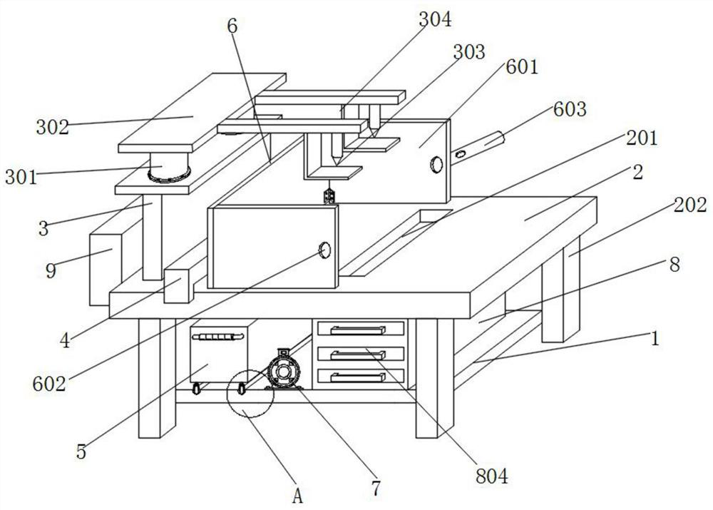
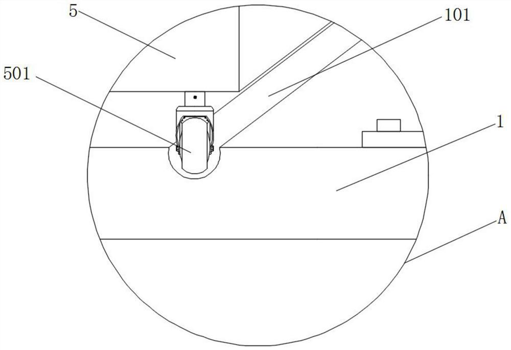
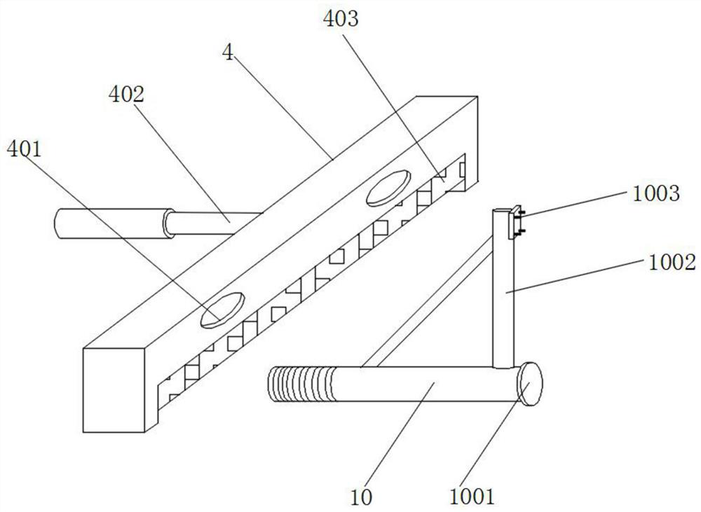
[0037] see Figure 1-Figure 7 , an embodiment provided by the present invention: a kind of electric device manufacturing equipment with waste recycling, including a bottom plate 1, a processing platform 2, a vertical plate 3, a carriage 4, a cleaning box 5, a protective shield 6, and a waste recycling cabinet 8 and threaded rod 10, the four corners of the bottom of the processing platform 2 are welded with support legs 202, the processing platform 2 can provid...


PUM


Abstract

The invention discloses power device manufacturing equipment with a waste recovery function. The power device manufacturing equipment with the waste recovery function comprises a bottom plate, a machining platform, a longitudinal plate, a protective blocking cover, a waste recovery cabinet and a threaded rod. Supporting legs are welded to the four corners of the bottom of the machining platform, a cleaning box is fixed to the tops of moving wheels, and the waste recovery cabinet is welded to the surface of the top of the bottom plate. A sliding frame is welded to the end, away from a fixing plate, of an electric telescopic rod in the manner of penetrating through the longitudinal plate, the threaded rod is connected to the interior of the sliding frame through an embedding opening, a triangular connecting frame is welded to the top of the threaded rod, and a connecting piece is welded to the surface of the side, away from the sliding frame, of the triangular connecting frame. The surface of the side, away from the sliding frame, of the connecting piece is detachably connected with the protective blocking cover through a bolt. By arranging the waste recovery cabinet, the collected waste can be subjected to soaking, dust removal, screening and corresponding wastewater purification treatment, so that subsequent classification and utilization of the waste are facilitated, the wastewater treatment cost is reduced, and water pollution is also avoided.

Description

technical field [0001] The invention relates to the technical field of manufacturing equipment, in particular to a power device manufacturing equipment with waste recycling. Background technique [0002] As an integral part of electronic products, power devices are usually small and precise parts. The processing process needs to go through multiple processes. In the process of power devices, welding is often used in the process of processing, but welding occurs due to improper operation. Waste products, at this time, the high temperature generated by the welding torch will cause the metal surface of the processed waste products to oxidize with the oxygen in the air, so that the surface of the power device will produce metal oxides, because the oxides will tarnish the metal parts and the surface will become rough. It is easier to accumulate dust, and the accumulation of dust will easily lead to the decline of the heat dissipation function of power devices, thus affecting the ...

Claims


Application Information

Patent Timeline
Patent Type & Authority Applications(China)
IPC IPC(8): B23K37/02B23K37/00B08B1/00B08B3/12B08B13/00
CPCB23K37/0247B23K37/00B08B1/00B08B3/12B08B13/00Y02P70/10
Inventor 甘骥平
Owner 广州渺钛新材料科技有限公司
Why Eureka
Try Eureka