Roller kiln cooling system for foamed ceramic production

A foamed ceramics and cooling system technology, applied in the field of kiln thermal engineering, can solve the problems of increased product cracking, low thermal conductivity, and uneven pore size of foamed ceramics, so as to achieve good uniformity of pores, stable cooling process, Effect of reducing debugging loss

Active Publication Date: 2021-05-07
FOSHAN JINYI GREEN ENERGY NEW MATERIAL TECH CO LTD +1
View PDF7 Cites 1 Cited by
  • Summary
  • Abstract
  • Description
  • Claims
  • Application Information

AI Technical Summary

Problems solved by technology

[0004] First of all, foamed ceramics will expand and foam during high-temperature sintering, and the foaming process will be affected when the quenching wind hits the hot foamed ceramic body
Moreover, the powder sintering process is mostly used in the production of existing foamed ceramics, and there are many gaps between the refractory kiln furniture used. When the quenching zone is injected with cold air to cool the plate, the quenching air pressure and air volume will be increased when the quenching zone passes through the plate gap and the thermocouple passes through the quenching zone. Larger changes will also affect the forward and backward movement of the zero pressure position, resulting in temperature fluctuations in the firing zone, which will adversely affect the foaming process of foamed ceramics and affect the foaming thickness of the product
[0005] Secondly, foamed ceramics are mostly used as masonry materials, and their volume will expand many times after being fired in a firing zone. structure, low thermal conductivity, therefore, when the rapid cooling wind hits the hot foamed ceramic body, the surface layer will cool down rapidly, while the internal temperature is still high, so the surface layer is rapidly cooled and solidified, while the interior is still at high temperature. Foaming causes stress difference inside and outside, causing cracking, and this also makes the pore size of the foamed ceramics uneven, and the internal pore size will be larger than the external pore size, which further increases the stress accumulation and increases the cracking defect of the product

Method used


Image

  • Roller kiln cooling system for foamed ceramic production
  • Roller kiln cooling system for foamed ceramic production
  • Roller kiln cooling system for foamed ceramic production

Examples


Embodiment Construction

[0028] The solutions of the present invention will be described in detail below in conjunction with the drawings and specific implementation methods.

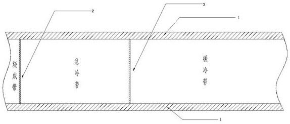
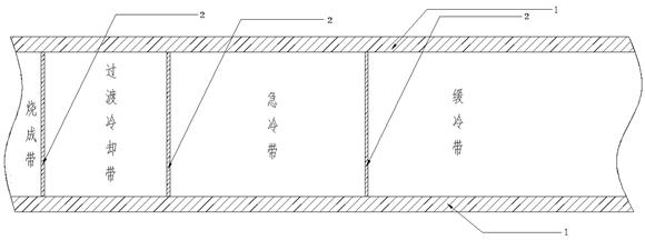
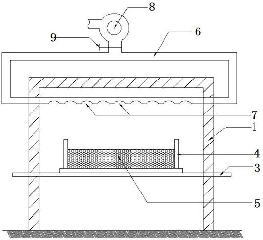
[0029] Refer to attached figure 1 And attached image 3 , with figure 1 It is a structural schematic diagram of the existing conventional roller kiln cooling system. The cooling system of the roller kiln refers to the collection of facilities from the kiln firing zone to the kiln tail to control the internal temperature drop of the kiln. After being fired in the firing zone, the ceramic body enters the cooling system to cool down. In the initial stage, the conventional wall and floor tile products can be quickly cooled to about 700°C. The volume change associated with the crystal transformation before 573°C is small, so rapid cooling can be carried out. Correspondingly, in the quenching zone immediately after the firing zone, a large amount of cold air is blown into the ceramics by an external blower in the quenching zone. T...


PUM


Abstract

The invention relates to the field of kiln thermal engineering, in particular to a roller kiln cooling system for foamed ceramic production. The roller kiln cooling system comprises a transition cooling zone, a quenching zone and a slow cooling zone which are sequentially arranged in a roller conveying direction, the transition cooling zone is positioned at the rear end of a roller kiln firing zone, and a fire barrier for separating flames is arranged between the transition cooling zone and the roller kiln firing zone. A quenching air pipe extending into a kiln cavity of a roller kiln is arranged on the side wall of the kiln of the quenching zone, one end of the quenching air pipe extends into the kiln cavity, the opening direction of the quenching air pipe is parallel to the top face of a foaming ceramic green body, the other end of the quenching air pipe is connected with an air blower, and external cold air is extracted through the air blower and sent into the kiln cavity of the quenching zone. According to the roller kiln cooling system for foamed ceramic production, the foamed ceramic cooling process can be more stable, the uniformity of air holes is better, and then the performance of foamed ceramic products is improved; and in addition, the superior rate of the products is greatly improved, the error-tolerant rate of the process and the formula is increased, and the debugging loss caused by formula adjustment is reduced.

Description

technical field [0001] The invention relates to the field of kiln thermal engineering, in particular to a roller kiln cooling system for the production of foamed ceramics. Background technique [0002] Roller kiln is a commonly used kiln equipment for the production of foamed ceramics. It uses rotating refractory rollers as the conveying medium to drive the green body to move from the kiln head to the kiln tail to complete sintering. In order to improve production efficiency and make better use of heat energy, the roller kiln is equipped with a cooling system to cool the fired green body. [0003] Refer to attached figure 1 , with figure 1 It is a structural schematic diagram of the cooling system of the existing conventional roller kiln, which includes two parts, namely the quenching zone and the slow cooling zone. In the slow cooling zone, at least a fire wall 2 is provided between the rapid cooling zone and the firing zone. In the quenching zone, there is a cold air p...

Claims


Application Information

Patent Timeline
Patent Type & Authority Applications(China)
IPC IPC(8): F27B9/12F27B9/30
CPCF27B9/12F27B9/30F27B2009/124F27M2001/1504F27M2003/04
Inventor 邓波江峰张国涛
Owner FOSHAN JINYI GREEN ENERGY NEW MATERIAL TECH CO LTD
Why Eureka
Try Eureka