Fire monitor motor driving and protecting circuit

A motor drive and protection circuit technology, applied in emergency protection circuit devices, electric components, DC motor rotation control and other directions, can solve problems such as driver burnout, fire monitor stuck, motor burnout, etc. The effect of distance control

Pending Publication Date: 2021-05-07
SICHUAN TECH & BUSINESS UNIV
View PDF10 Cites 0 Cited by
  • Summary
  • Abstract
  • Description
  • Claims
  • Application Information

AI Technical Summary

Problems solved by technology

[0002] In the electric control fire monitor, it is necessary to control the left and right, up and down swing of the fire monitor head, and the swing angle is often limited by the mechanical limit mechanism. When the fire monitor swings to the limit position in a certain direction, the fire monitor will It will be stuck. If you continue to provide driving force to the motor of the fire monitor at this time, the motor will be burned or the driver will be overheated and burned
However, fire monitors implemented by mechanical limit methods do not have the ability to provide feedback signals. Therefore, other methods are needed to detect whether the motor is already at the limit position, so as to stop providing driving force to the drive motor in time

Method used


Image

  • Fire monitor motor driving and protecting circuit
  • Fire monitor motor driving and protecting circuit
  • Fire monitor motor driving and protecting circuit

Examples


Embodiment 1

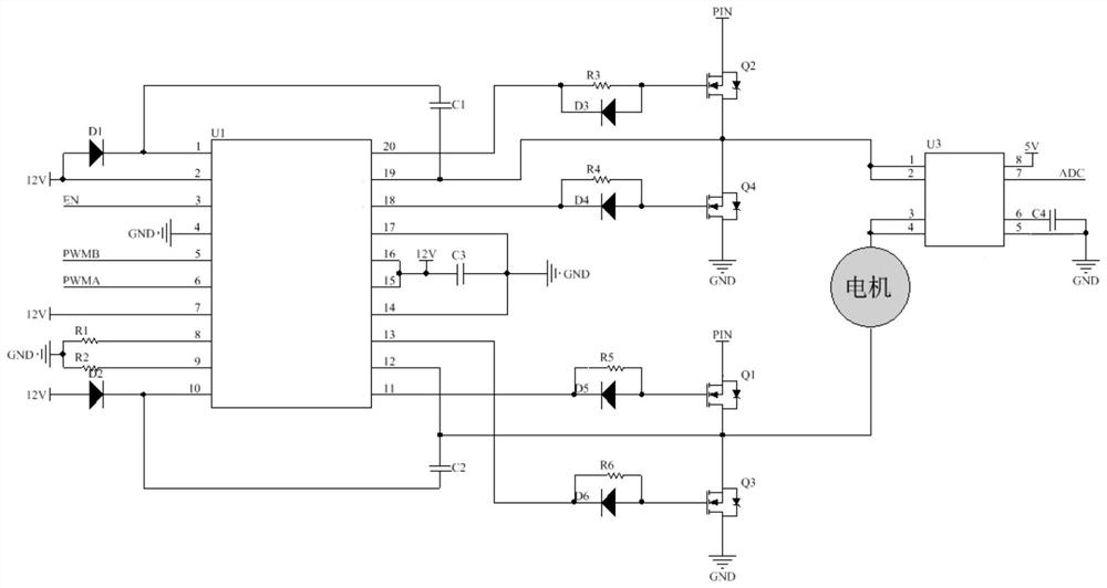
[0030]Such asfigure 2 The drive protection circuit diagram provided by the present invention, the H full bridge main circuit consists of the MOSFET of Q1, Q2, Q3, Q4 IRF3205PBF, and the input voltage of the main circuit is 24V, Q1, Q3 to receive the positive connection with the load motor. The Q2 and Q4 are connected to the load motor negative connection. Among them, IRF3205PBF is a HexFET N channel power MOSFET with extremely low on-resistance and rapid switching performance.

[0031]The driving signal of the four switch tubes in the main circuit achieves, Q1, Q3, the gate of Q1, Q3, and the gate of Q2, Q4 are connected to the entire bridge, respectively, and the gate of Q2, Q4, respectively, with the full bridge driver HIP4081A U1. The output pins 20 and 18 of the driver U1 are connected, and one gate resistance is connected between the gate and the full bridge driver, and a diode, that is, the gate connection of Q1 is connected to the gate resistance. The R4 and D4 of R6 and D3, Q4 ...

Embodiment 2

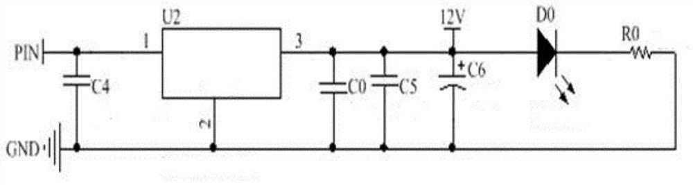
[0039]On the basis of the first embodiment, in order to ensure the normal operation of the full bridge driver U1, the MC7812 power supply regulator chip U2 is designed to provide a working voltage 12V for the driving circuit, such asimage 3 As shown, the input voltage of the linear regulator circuit is 24V, that is, the PIN interface input 24V voltage, the input is provided with one end of the input capacitance C4, C4, 1 pin connected to the MC7812 power supply regulator chip U2, one end and 2 pin ground Connection, there is also a capacitor C0, C5, and C6 between the 3-pin and 2 pins. For filtering and regulating, the circuit output 12V regulated power supply, the output terminal of the linear regulator circuit is connected in parallel with a light emitting diode D0. And the output voltage positive electrode of the light-emitting diode D0 and the output voltage of the linear regulator circuit is connected, the cathode is connected to one end of the partial pressure resistance, and ...

Embodiment 3

[0042]On the basis of Example 1, ifFigure 5 As shown, in the process of rotation of the motor in the real-time monitoring, the working condition detection problem when the motor is blocked, and when the motor is working, the motor current is monitored by the Hall current monitoring the chip in real time. In the present embodiment, when the motor current is less than 3A, the motor is operating normally; when the motor current is greater than 10A, the motor is blocked, which is the protective motor and the driving circuit. When the motor current reaches 7A, by changing the PWM pulse width, limit input The voltage of the motor is thus realized current limitation. If the current continues to exceed 7A, and the duration reaches 3s, the PWM input is cut off, and the power input of the motor is turned off to achieve the purpose of the protection motor.


PUM


Abstract

The invention belongs to the technical field of electric fire monitor control, and discloses a fire monitor motor driving and protecting circuit. The fire monitor motor driving and protecting circuit comprises a CPU, a driving circuit connected with the CPU, a power supply and a full-bridge circuit connected with the power supply and is used in a 24V direct-current working environment, wherein the driving circuit adopts an HIP4081A full-bridge driver. The motor driving and protecting circuit further comprises a linear voltage stabilizing circuit, a Hall current monitoring chip and an infrared temperature sensor, wherein the input end of the linear voltage stabilizing circuit is connected with the power supply, the output end of the the linear voltage stabilizing circuit is connected with the driving circuit, the linear voltage stabilizing circuit is used for reducing and stabilizing power voltage and outputting the power voltage for the driving circuit to use, the Hall current monitoring chip is connected with the output end of the full-bridge circuit in series and used for monitoring motor current and positive and negative rotation of the motor, and the infrared temperature sensor is connected with the CPU and used for monitoring the working temperature of the motor. Positive and negative rotation control of the motor can be realized, and the working condition of the motor can be timely known through current monitoring.

Description

Technical field[0001]The present invention relates to the field of electric fire gun control technology, and specific to a fire gun motor drive and protection circuit.Background technique[0002]In the fire gun of electric control, it is necessary to control the gun head of the fire gun, swing up and down, and the angle of swing is often limited by the mechanical limit mechanism. When the fire gun is swung to a limit position, the fire cannon will Will be killed, if it continues to provide driving force to the fire gun motor at this time, the motor will cause the motor to be burned or the drive is overheating. However, the fire cannon implemented using a mechanical limit method does not have the ability to provide feedback signals. Therefore, it is necessary to detect whether the motor is already in an extreme position, thereby stopping the drive motor to continue providing driving forces.Inventive content[0003]It is an object of the present invention to provide a fire gun motor drive...

Claims


Application Information

Patent Timeline
Patent Type & Authority Applications(China)
IPC IPC(8): H02P7/03H02K11/27H02K11/25H02H7/08
CPCH02P7/04H02K11/27H02K11/25H02H7/0811H02H7/0838
Inventor 徐思燕龚名茂
Owner SICHUAN TECH & BUSINESS UNIV
Why Eureka
Try Eureka