
Rubber grinding machine

A grinding machine and rubber technology, used in grinding frames, grinding machine parts, grinding machines, etc., can solve the problems of low grinding quality, adverse human health, and affecting grinding efficiency.

Inactive Publication Date: 2021-05-11
南京亿柏年贸易有限公司
View PDF0 Cites 1 Cited by
  • Summary
  • Abstract
  • Description
  • Claims
  • Application Information

AI Technical Summary

Problems solved by technology

[0005] Aiming at the deficiencies of the prior art, the present invention provides a rubber grinding machine, which solves the problem that a large amount of dust will be generated when the rubber is polished, and the dust will adhere to the surface of the grinding tool, affecting the grinding efficiency, and a large amount of dust will fall Afterwards, the accumulation will leave grinding marks on the surface of the rubber product during the grinding process, which will affect the smoothness of the surface, and then make the grinding quality low, and the dust will fly. After the human body inhales it, it is not conducive to human health and reduces the use. performance problem

Method used


Image

  • Rubber grinding machine
  • Rubber grinding machine
  • Rubber grinding machine

Examples


Embodiment example 1

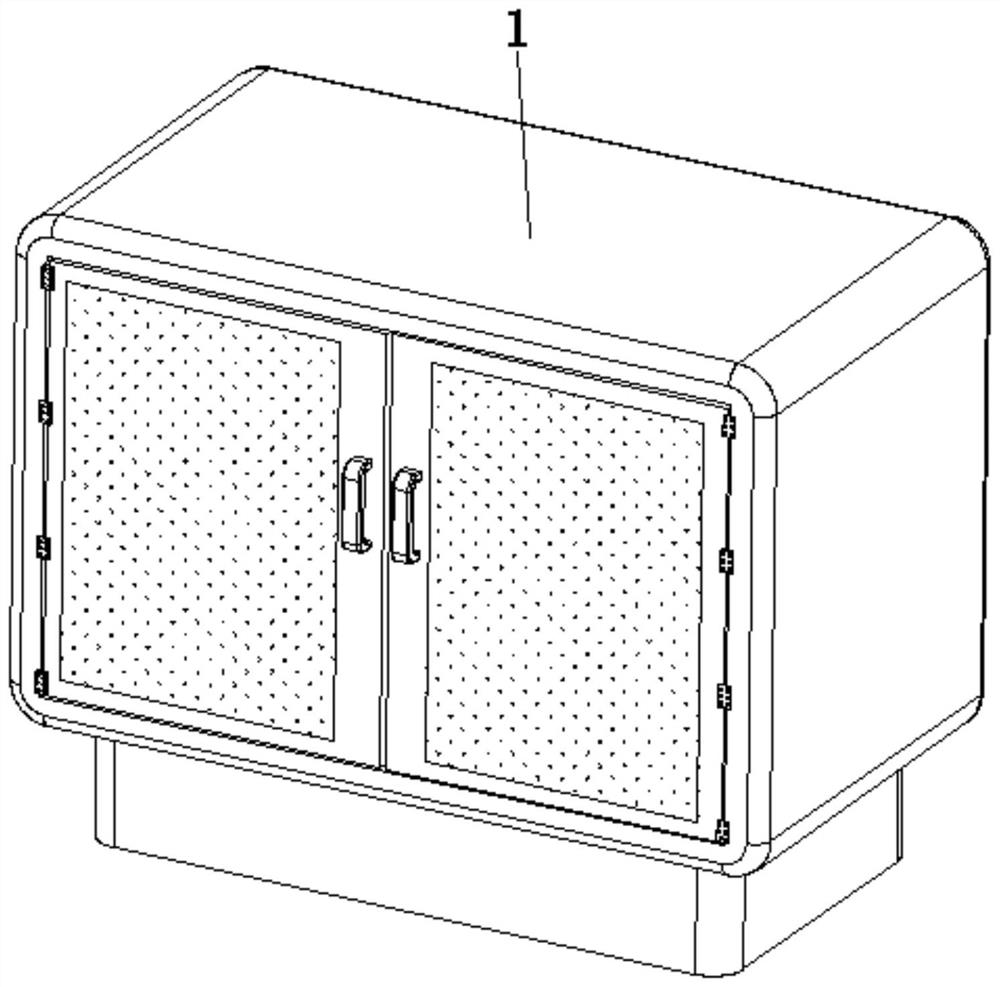
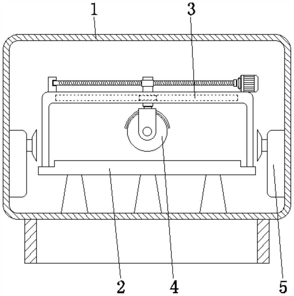
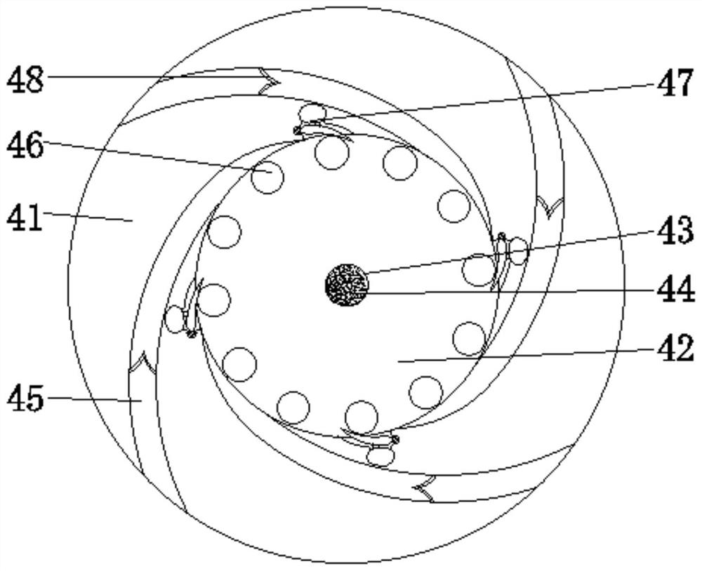
[0033] see Figure 1-7 , the present invention provides a technical solution: a rubber grinding machine, comprising a chassis 1, a workbench 2, a support drive mechanism 3, a grinding device 4, and a vacuum cleaner 5, the workbench 2 is fixed at the bottom center of the inner wall of the chassis 1, and the grinding device 4 is fixed on the top of the workbench 2 through the support drive mechanism 3, the vacuum cleaner 5 is fixed on both sides of the inner wall of the cabinet 1, and the grinding device 4 is provided with a grinding roller 41, a cylindrical inner cavity 42, an exhaust hole 43, a filter screen 44, and a flow guide Air channel 45, friction ball 46, dust removal device 47, filter device 48, cylindrical inner chamber 42 is set in the inner central position of grinding roller 41, exhaust hole 43 is opened in one end of grinding roller 41, filter screen 44 is fixed on the exhaust hole 43, the guide air passage 45 is set inside the grinding roller 41 and communicates ...

Embodiment example 2

[0038] The filtering device 48 is provided with an arc surface housing 481, a flow guide 482, a filter plate 483, an air inlet 484, and an air outlet 485. The flow guide 482 is fixed on one side of the surface of the arc surface housing 481, and the filter plate 483 is fixed In the inside of the curved shell 481 and the inside of the flow guide 482, the air inlet 484 and the air outlet 485 are respectively opened on the surface of the flow guide 482 and the surface of the curved shell 481, and are used to change the path of the air flow and If the speed is moderately reduced, the large particle dust can be filtered in time first, so as not to affect the subsequent collection of dust and avoid blockage.

[0039] When in use, first put the rubber to be polished on the workbench 2. At this time, the motor drives the grinding device 4 to rotate at a high speed, and is driven by the supporting drive mechanism 3 to perform grinding, and then the vacuum cleaner 5 is turned on for dust...


PUM


Abstract

The invention discloses a rubber grinding machine which comprises a machine box, a workbench, a supporting driving mechanism, a grinding device and dust collectors, the grinding device is fixed to the top of the workbench through the supporting driving mechanism, the dust collectors are fixed to the two sides of the inner wall of the machine box, exhaust holes are formed in one end of a grinding roller, and filter screens are fixed into the exhaust holes. A flow guide air channel is formed in the grinding roller and communicates with an cylindrical inner cavity, a friction ball is arranged in the cylindrical inner cavity, a dust removal device is arranged in the grinding roller and located on the inner wall of the cylindrical inner cavity, and a filtering device is arranged in the flow guide air channel and close to a port. The invention relates to the technical field of rubber polishing. According to the rubber grinding machine, the purpose of dust removal is achieved, dust can be removed step by step, dust accumulation and diffusion are reduced, grinding cracks are avoided, the grinding quality is high, meanwhile, dust suction by a human body is reduced, human health is facilitated, and the use performance is improved.

Description

technical field [0001] The invention relates to the technical field of rubber grinding, in particular to a rubber grinding machine. Background technique [0002] Rubber: Highly elastic polymer material with reversible deformation. It is elastic at room temperature, can produce large deformation under a small external force, and can return to its original shape after the external force is removed. Rubber is a completely amorphous polymer with a low glass transition temperature and often a large molecular weight, greater than hundreds of thousands. Rubber grinding machine is an important processing equipment in the modern rubber processing industry. Its function is mainly to grind rubber products, making the surface of rubber products smoother, better streamlined, and improving user experience. The general structure of the rubber grinding machine is to configure a rotating blade or grinding wheel on the motor, and use the motor to drive the blade to rotate or the grinding wh...

Claims


Application Information

Patent Timeline
Patent Type & Authority Applications(China)
IPC IPC(8): B24B9/20B24B41/06B24B47/12B24B41/02B24B55/06B08B15/04B08B6/00B01D50/00
CPCB01D50/00B08B6/00B08B15/04B24B9/20B24B41/02B24B41/06B24B47/12B24B55/06
Inventor 胡浩
Owner 南京亿柏年贸易有限公司
Learn More