Sludge crushing and drying device

A drying and sludge technology, applied in the direction of dehydration/drying/thickened sludge treatment, grain treatment, etc., can solve problems such as easy caking, achieve the effects of shortening equipment life, beautiful environment protection, and reducing drying efficiency

Active Publication Date: 2021-05-14
ZHEJIANG SANLIAN ENVIRONMENT MACHINERY EQUIP
View PDF9 Cites 0 Cited by
  • Summary
  • Abstract
  • Description
  • Claims
  • Application Information

AI Technical Summary

Problems solved by technology

[0005] Aiming at the problem that in the prior art, when the moisture content is reduced to about 60% during the sludge crushing process, the sludge will be in the cementation stage and agglomeration is easy to occur. The invention provides a sludge crushing and drying device, which divides the stirring propulsion rod arranged along the length dire...

Method used


Image

  • Sludge crushing and drying device
  • Sludge crushing and drying device
  • Sludge crushing and drying device

Examples


Embodiment 1

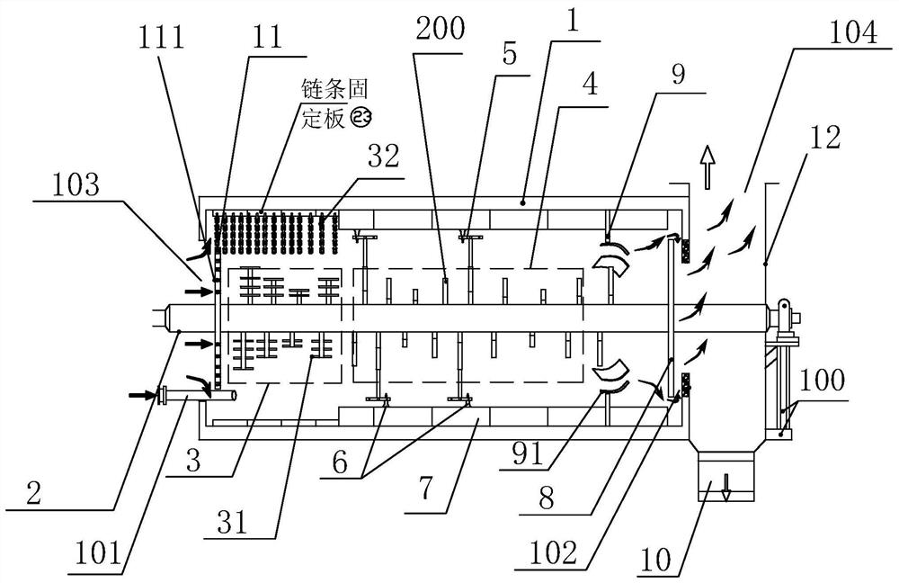
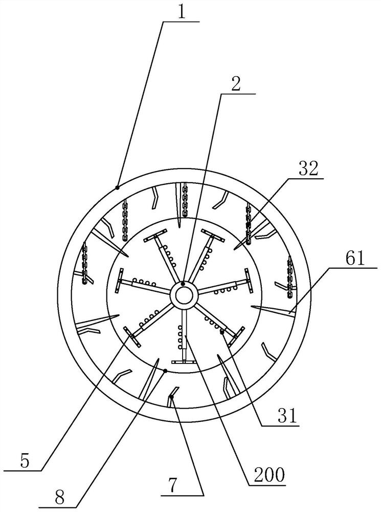
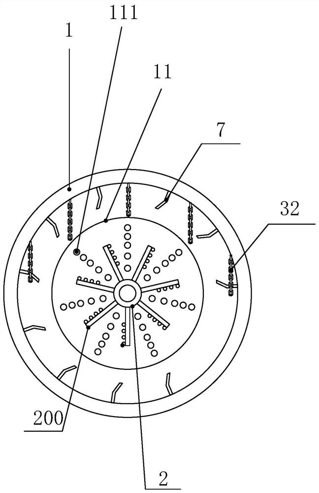
[0029] Such as figure 1 , 2 As shown, a sludge crushing and drying device includes a machine base 100, a drying drum 1 is placed horizontally on the machine base, an inner rotating shaft 2 is arranged inside the drying drum, and a stirring propulsion device is arranged radially on the inner rotating shaft. The rod 200 assembly, the stirring propulsion rod assembly includes a propulsion section 3 and a fine crushing section 4 along the extension direction of the inner rotating shaft, a material inlet 101 is arranged at the end of the drying drum close to the propulsion section, and a hot smoke inlet 103 is arranged above the material inlet, A fine crushing runner is arranged at the tail end of the stirring propulsion rod in the fine crushing section. The stirring propulsion rod sequentially includes a connecting part 201, a crushing part 202 and an extension part 203 along the length direction. The connecting part is connected to the inner rotating shaft. The cross section of ...

Embodiment 2

[0035] The difference from Embodiment 1 is that in this embodiment, the lengths of the crushing rods on both sides of the extension section are not equal, including the long end and the short end. Under this unbalanced structure, no matter the length After the end or the short end collides with the stop rod, the fine crushing rotor can be rotated at a variable speed, which makes the fine crushing rotor effectively assist the high-temperature hot air in the drying drum to form turbulent flow and improve the drying effect. At the same time, since the contact area between the long end and the sludge material is larger, when the short end collides with the blocking rod, since the long end and the short end have the same angular velocity, the free end of the long end has Higher linear velocity, according to the momentum formula, the momentum of the long rod is significantly improved, which can more effectively hit the sludge particles for crushing. Correspondingly, when the long en...


PUM


Abstract

The invention discloses a sludge crushing and drying device which comprises a machine base; a drying rotary drum is transversely arranged on the machine base, an inner rotating shaft is arranged in the drying rotary drum, a stirring pushing rod assembly is arranged on the inner rotating shaft in the radial direction, and the stirring pushing rod assembly comprises a pushing section and a fine crushing section in the extending direction of the inner rotating shaft; and a material inlet is formed in one end, close to the pushing section, of the drying rotary drum, a hot smoke inlet is formed above the material inlet, and a fine crushing rotary wheel is arranged at the tail end of the stirring pushing rod in the fine crushing section. The stirring pushing rod arranged in the length direction of the drying rotary drum is divided into the pushing section and the fine crushing section, refining and labor division are achieved, the fine crushing rotary wheel at the tail end of the fine crushing section is used for fully crushing sludge in a cementing stage, the treatment effect of a sludge crushing and drying device is effectively improved, the drying efficiency is improved, and the service life of equipment is prolonged.

Description

technical field [0001] The invention relates to the technical field of sludge treatment, in particular to a sludge crushing and drying device. Background technique [0002] With the large-scale construction of modern sewage treatment plants, sludge production has increased rapidly. These sludges have a high water content (generally 98%), and the water content after dehydration is still greater than 80%, which is not easy to handle. If not properly treated and disposed of, it will cause secondary pollution to the surrounding environment of the dumping area. Rational treatment of sludge is an inevitable requirement to maintain the beautiful environment around us and protect our health. Anaerobic digestion, high-temperature composting, incineration and landfill are the most commonly used methods for sludge treatment and disposal, but the direct use of sludge with high moisture content in composting and landfill will easily cause new environmental pollution, and sludge incinera...

Claims


Application Information

Patent Timeline
IPC IPC(8): C02F11/13B02C13/02B02C13/28
CPCC02F11/13B02C13/02B02C13/28B02C2201/06
Inventor 项乐群李秀朝纪伟勇吴天炳蓝丽梅
Owner ZHEJIANG SANLIAN ENVIRONMENT MACHINERY EQUIP
Why Eureka
Try Eureka