
Integrated packaging antenna and packaging method thereof

An integrated packaging and antenna technology, applied in the antenna grounding device, antenna, antenna support/installation device, etc., can solve the problem of poor heat dissipation of the adapter board and cannot be used as a mechanical support.

Active Publication Date: 2021-05-18
SHANGHAI SPACEFLIGHT ELECTRONICS & COMM EQUIP RES INST
View PDF6 Cites 3 Cited by
  • Summary
  • Abstract
  • Description
  • Claims
  • Application Information

AI Technical Summary

Problems solved by technology

[0004] The purpose of the present invention is to provide an integrated package antenna and its packaging method, which solves the problem that the commonly used adapter board has relatively poor heat dissipation and cannot be used as a mechanical support, and at the same time completes the integration of the substrate and the housing to realize the structural functions of the substrate and the housing Integration, obtaining the integration, miniaturization and lightweight packaging of antenna module and radio frequency module

Method used


Image

  • Integrated packaging antenna and packaging method thereof
  • Integrated packaging antenna and packaging method thereof
  • Integrated packaging antenna and packaging method thereof

Examples


Embodiment 1

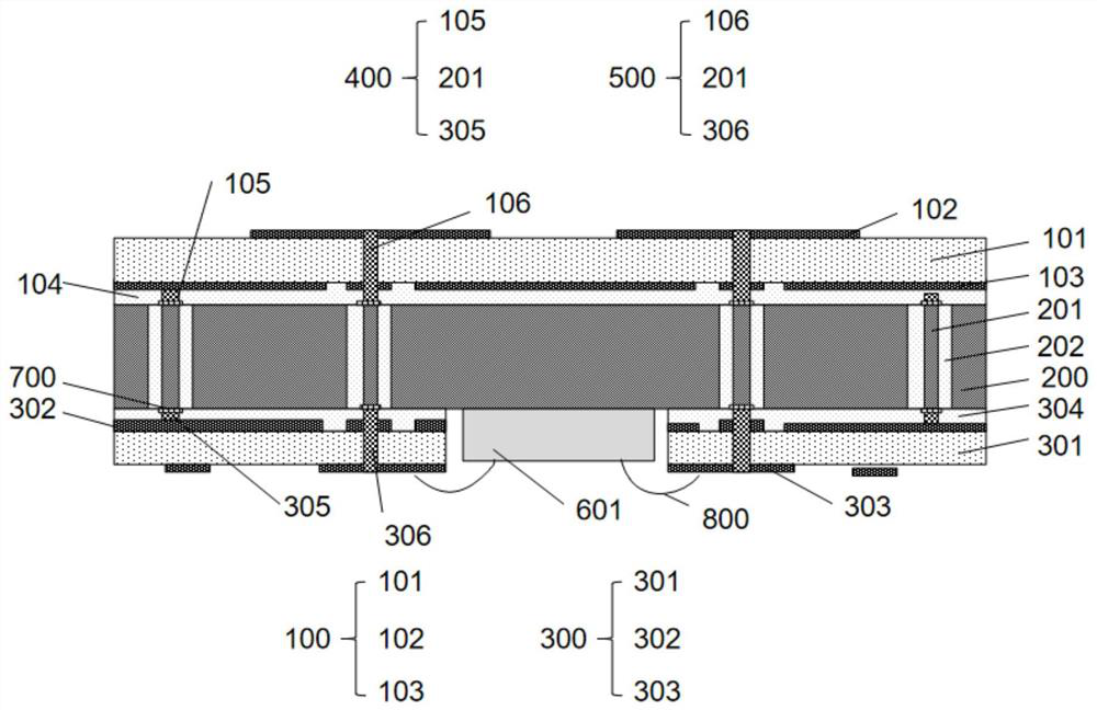
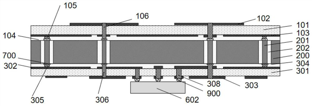
[0074] see Figure 1 to Figure 2 As shown, this embodiment provides an integrated package antenna, including at least one semiconductor chip and an antenna module substrate 100, an aluminum-silicon adapter plate 200, and a radio frequency module substrate 300 laminated sequentially from top to bottom:

[0075] The material of the aluminum-silicon adapter plate 200 is selected as Al30Si70, and the aluminum-silicon adapter plate 200 is placed between the antenna module substrate 100 and the radio frequency module substrate 300 to provide mechanical support and electrical interconnection. The aluminum-silicon adapter plate has high heat dissipation, The advantages of low thermal expansion coefficient and high strength can reduce costs and improve heat dissipation compared with traditional silicon interposers or LTCC substrates.

[0076] The antenna module substrate 100 includes an antenna layer LCP substrate 101 and an antenna pattern layer 102 and an antenna ground layer 103 res...

Embodiment 2

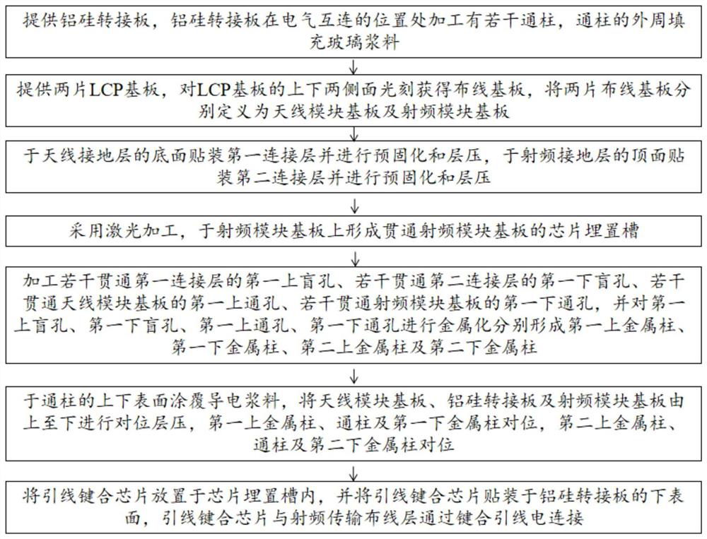
[0087] see Figure 3 to Figure 11 , based on the same inventive concept, this embodiment provides a packaging method for an integrated packaged antenna, including the following steps:

[0088] S1: see Figure 4 As shown, an Al-Si adapter plate 200 is provided, and the Al-Si adapter plate 200 is processed with a number of via posts 201 at the position of electrical interconnection, and the outer circumference of the via posts 201 is filled with glass paste 202. In this embodiment, Al-Si The material of the adapter plate 200 is Al30Si70, and the thickness of the Al-Si adapter plate 200 is 0.1-1 mm;

[0089] In this embodiment, the step S1 specifically includes the following:

[0090] S11: Provide aluminum-silicon substrate;

[0091] S12: Use a laser to ablate the outer peripheral area of ​​the electrical interconnection of the aluminum-silicon substrate to obtain through-pillars for electrical interconnection and grooves surrounding the through-pillars. The depth of the groov...

Embodiment 3

[0102] see Figure 12 to Figure 18 As shown, based on the same inventive concept, this embodiment also provides a packaging method for an integrated packaged antenna, including the following steps:

[0103] A1: Provide an aluminum-silicon adapter board 200. The aluminum-silicon adapter board 200 is processed with a number of through posts 201 at the position of electrical interconnection, and the outer circumference of the through posts 201 is filled with glass paste 202. The material of the connecting plate 200 is Al30Si70, and the thickness of the aluminum-silicon connecting plate 200 is 0.1-1 mm;

[0104] In this embodiment, the step A1 specifically includes the following:

[0105] A11: Provide aluminum silicon substrate;

[0106] A12: Use a laser to ablate the outer peripheral area of ​​the electrical interconnection of the aluminum-silicon substrate to obtain through-pillars for electrical interconnection and grooves surrounding the through-pillars. The depth of the gro...


PUM


Abstract

The invention discloses an integrated packaging antenna comprising at least one semiconductor chip, an antenna module substrate, an aluminum-silicon adapter plate and a radio frequency module substrate, the antenna module substrate, the aluminum-silicon adapter plate and the radio frequency module substrate are sequentially laminated from top to bottom, and the antenna module substrate comprises an antenna layer LCP substrate, an antenna pattern layer and an antenna grounding layer, wherein the antenna pattern layer and the antenna grounding layer are arranged on the top surface and the bottom surface of the antenna layer LCP substrate. the radio frequency module substrate comprises a radio frequency layer LCP substrate, a radio frequency grounding layer and a radio frequency transmission wiring layer, and the radio frequency grounding layer and the radio frequency transmission wiring layer are arranged on the top face and the bottom face of the radio frequency layer LCP substrate respectively. The problem that a common adapter plate is relatively poor in heat dissipation and cannot serve as a mechanical support is solved; compared with a traditional silicon adapter plate or an LTCC substrate, the cost can be reduced, and heat dissipation can be improved; meanwhile, integration of the substrate and the shell is completed, structural function integration of the substrate and the shell is achieved, and integration, miniaturization and light-weight packaging of an antenna module and a radio frequency module are achieved.

Description

technical field [0001] The invention belongs to the technical field of electronic packaging, and in particular relates to an integrated packaging antenna and a packaging method thereof. Background technique [0002] With the rapid development of wireless communication technology, especially the wide application of mobile communication and wireless local area network, the encapsulation requirements for radio frequency transceiver systems are also getting higher and higher, requiring small volume, low cost, and high integration. [0003] For the interconnection of antennas and systems, it is usually implemented after separate design and assembly. Although this is helpful for the separate design of each antenna and system, the interconnection loss between the antenna and the module will greatly increase the size and cost of the system. Contents of the invention [0004] The purpose of the present invention is to provide an integrated package antenna and its packaging method, ...

Claims


Application Information

Patent Timeline
Patent Type & Authority Applications(China)
IPC IPC(8): H01L23/66H01L23/367H01L23/538H01L21/768H01Q1/22H01Q1/38H01Q1/48H01Q1/00
CPCH01L23/66H01L23/5386H01L21/76895H01L23/3677H01Q1/2283H01Q1/38H01Q1/48H01Q1/02
Inventor 罗燕高求丁蕾刘凯黄一王立春曹向荣陈凯
Owner SHANGHAI SPACEFLIGHT ELECTRONICS & COMM EQUIP RES INST
Learn More