
Pump laser packaging structure and packaging method

A technology for pumping lasers and packaging structures, which is applied in laser devices, semiconductor laser devices, lasers, etc., and can solve problems such as heat generation and inability to completely absorb light

Inactive Publication Date: 2021-05-18
Shandong Huaguang Optoelectronics Co. Ltd.
View PDF10 Cites 3 Cited by
  • Summary
  • Abstract
  • Description
  • Claims
  • Application Information

AI Technical Summary

Problems solved by technology

[0006] Aiming at the deficiencies of the prior art, the present invention provides a pump laser packaging structure, which effectively solves the problems of incomplete absorption of light and heat generation by residual light

Method used


Image

  • Pump laser packaging structure and packaging method
  • Pump laser packaging structure and packaging method
  • Pump laser packaging structure and packaging method

Examples


Embodiment 1

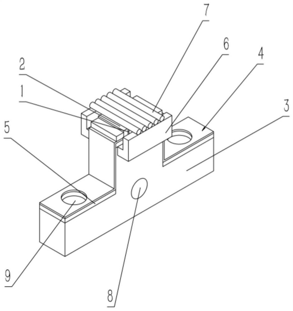
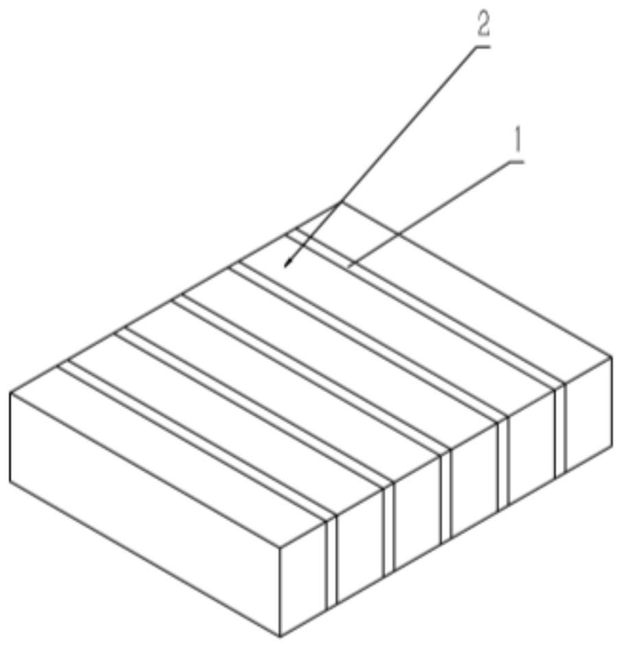
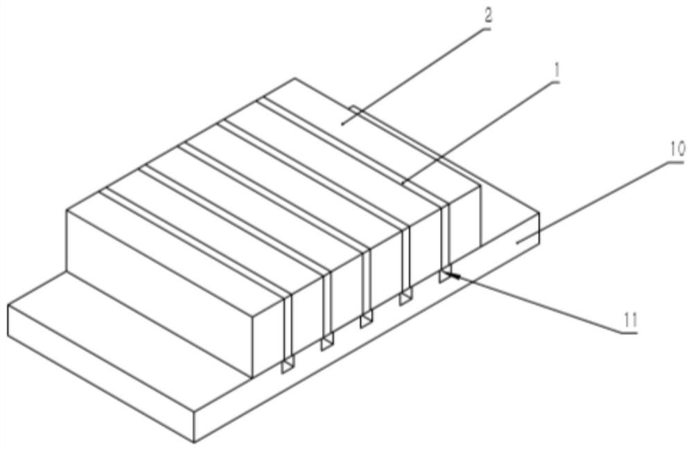
[0036] Such as Figure 1-4 As shown, a pump laser package structure, including mini bar 1, tungsten copper heat sink 2, AlN ceramic sheet 10, heat dissipation heat sink 3 and electrode 4, mini bar 1 and tungsten copper heat sink 2 are welded to form a bar arrays, such as figure 2 As shown, the thickness of the tungsten-copper heat sink 2 is 0.3 mm, the length of the mini bar 1 is 3 mm, and the length of the mini bar is consistent with the length of the tungsten-copper heat sink. 4 is packaged to both ends of the heat dissipation heat sink through the electrode insulating sheet 5 . The length of the tungsten copper heat sink 2 is the same as the length of the mini bar. Considering the stress release and heat dissipation capability, W90Cu with a thermal conductivity of 188W / (m*K) and a CTE of 6.5ppm / K is selected as the tungsten copper heat sink material. The coefficient of thermal expansion (CTE) is basically the same as that of the bar material, ensuring stress relief durin...

Embodiment 2

[0039] A packaging structure for a pump laser, the structure is as described in Embodiment 1, the difference is that the thickness of the tungsten-copper heat sink 2 is 10 mm, and the length of the mini bar is 1 mm.

Embodiment 3

[0041] A pump laser packaging structure, the structure is as described in Embodiment 1, the difference is that the lens 7 is installed above the bar array, the lens is fixed by the spacer 6, the spacer 6 is fixed on the upper end of the heat sink 3, and the spacer The cross-section is L-shaped, and the number of pads is two. The two pads are symmetrically arranged on both sides of the upper end of the heat sink. The upper surface of the pads is parallel to the upper surface of the tungsten copper heat sink. A lens is arranged between the two pads. The lens 7 is an O-shaped cylindrical lens, which can be used for compression in the direction of the fast axis of the bar to obtain pump light with high beam quality. The lens 7 is used to focus and homogenize the light spot, so that the energy distribution of the laser is more concentrated and uniform, and the laser energy distribution is improved. The beam quality of the pump light improves the pump efficiency.


PUM

PropertyMeasurementUnit
lengthaaaaaaaaaa
thicknessaaaaaaaaaa

Abstract

The invention relates to a pump laser packaging structure and packaging method, and belongs to the technical field of semiconductor laser stack array packaging. The packaging structure comprises a mini bar, a tungsten copper heat sink, an AlN ceramic chip, a heat dissipation heat sink and electrodes, the mini bar and the tungsten copper heat sink are welded to form a bar array, the bar array is welded to the heat dissipation heat sink through the AlN ceramic chip, and the electrodes are packaged to the two ends of the heat dissipation heat sink through electrode insulation pieces. The light-emitting area of the packaged pump laser is matched with the end face of the crystal, the emitted light can completely enter a crystal bar to be pumped, and the problem of heat production caused by the fact that redundant light irradiates the side face of the crystal or other positions is solved.

Description

technical field [0001] The invention relates to a pump laser packaging structure and packaging method, belonging to the technical field of semiconductor laser stack packaging. Background technique [0002] Conduction-cooled semiconductor lasers have the advantages of small size, low price, high efficiency, and long life. They are mainly used in industrial pumping, material processing, medical beauty, and scientific research and military industries. In the field of pumping applications, it mainly focuses on the pumping of Nd:YAG, Nd:YVO4 and other crystals. For the application of crystal end pumping, the requirements for the packaging volume and integration of lasers are getting higher and higher. At present, the conduction cooling semiconductor lasers commonly used in the market are mainly packaged in centimeter bars, and the size in the period direction is basically fixed at 1cm. Small packaging area, but because the laser composed of centimeter bars cannot meet the volume...

Claims


Application Information

Patent Timeline
Patent Type & Authority Applications(China)
IPC IPC(8): H01S5/024H01S5/042H01S5/02315H01S5/40
CPCH01S5/02469H01S5/0425H01S5/4025
Inventor 付传尚开北超孙素娟徐现刚郑兆河
Owner Shandong Huaguang Optoelectronics Co. Ltd.
Learn More