Vapor deposition device and preparation method of carbon/carbon composite material

A carbon composite material and vapor deposition technology, which is applied in the field of vapor deposition device and carbon/carbon composite material preparation, can solve the problems of insufficient contact between carbon source gas and green body, low linear expansion coefficient and high preparation cost, and achieves good Material properties, development and application prospects, simple device structure, and high densification efficiency

Active Publication Date: 2021-05-25
CENT SOUTH UNIV
View PDF11 Cites 2 Cited by
  • Summary
  • Abstract
  • Description
  • Claims
  • Application Information

AI Technical Summary

Problems solved by technology

[0003] Chemical vapor deposition (CVD) is the preferred method for preparing high-performance carbon / carbon composite materials. The carbon / carbon composite materials prepared by this method have the advantages of high mechanical properties, good thermal conductivity, and low linear expansion coefficient. The key preparation technology of carbon composite materials, but the existing CVD process is not suitable for the densification of ultra-large and ultra-thick (1000mm×300mm×150mm or more) carbon / carbon composite materials. Not deep, resulting in the density of the green body after CVD is difficult to exceed 1.30g / cm 3 , the difference between inner and outer density exceeds 0.2g / cm 3 , the densification process cycle is long (about 600-800h), and the preparation cost is high

Method used


Image

  • Vapor deposition device and preparation method of carbon/carbon composite material
  • Vapor deposition device and preparation method of carbon/carbon composite material
  • Vapor deposition device and preparation method of carbon/carbon composite material

Examples


preparation example Construction

[0051] In addition, the present invention also provides a method for preparing a carbon / carbon composite material, comprising the following steps:

[0052] a. Prepare carbon fiber prefabricated body;

[0053] b. Carrying out primary graphitization treatment on the carbon fiber prefabricated body to obtain the carbon fiber green body;

[0054] c. Carrying out CVD densification treatment on the carbon fiber green body to obtain the CVD green body,

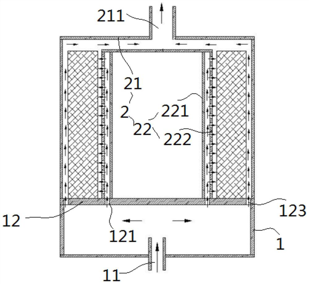
[0055] The CVD densification process is performed in the vapor deposition apparatus described above,

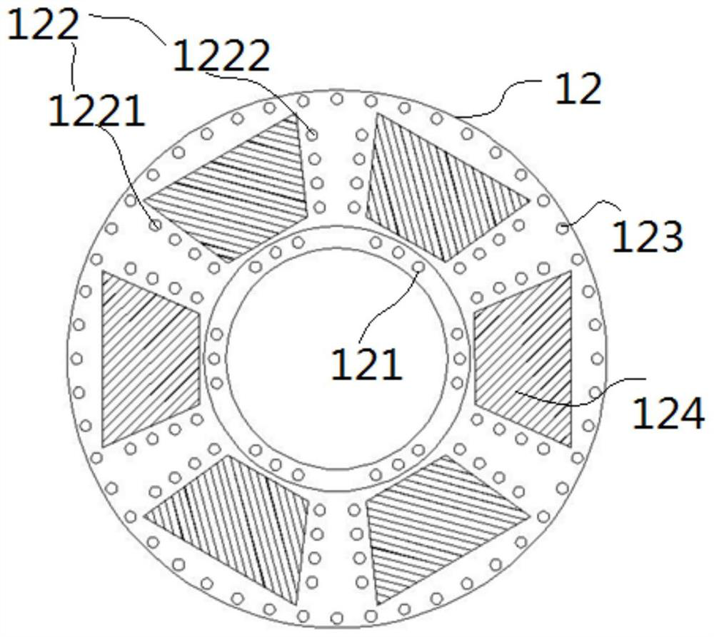
[0056] When charging, the carbon fiber blank is placed on the blank placement position 124 reserved between the second air inlet 1221 and the third air inlet 1222;

[0057] d. Perform secondary graphitization treatment on the CVD green body to obtain the primary product;

[0058] e. Finishing the primary product to obtain the finished product.

[0059] Preferably, the carbon source gas for CVD densification treatment is natural ...

Embodiment 1

[0073] a. Prepare 20 carbon fiber prefabricated bodies. The carbon fiber prefabricated body is a 2D needle-punched structure. A layer of PANCF non-weft cloth and a layer of PANCF non-weft cloth mesh are alternately laid, and the non-weft cloth is alternately laid at 0° / 90°. Made by continuous needle punching; the size of the carbon fiber preform is 1500mm×415mm×220mm, and the density is 0.58g / cm 3 ;

[0074] b. Carry out primary graphitization treatment on the carbon fiber prefabricated body to obtain the carbon fiber green body; put the carbon fiber prefabricated body into the heat treatment furnace, firstly evacuate, heat up to 2000°C and keep it warm for 2 hours, during which argon gas is filled, and the furnace pressure is 0.2-3KPa , to graphitize the carbon fiber preform, and then cool it naturally with the furnace;

[0075] c. Carrying out CVD densification treatment on the carbon fiber green body to obtain the CVD green body,

[0076] The CVD densification treatment i...

Embodiment 2

[0083] a. Prepare 10 pieces of carbon fiber prefabricated body. The carbon fiber prefabricated body is a 2D needle-punched structure. A layer of PANCF non-weft cloth and a layer of PANCF non-weft cloth mesh tire are alternately laid, and the non-weft cloth is alternately laid at 0° / 90°. Continuous needle punching; the size of the carbon fiber preform is 1200mm×350mm×200mm, and the density is 0.45g / cm 3 ;

[0084] b. Carry out primary graphitization treatment on the carbon fiber prefabricated body to obtain the carbon fiber green body; put the carbon fiber prefabricated body into the heat treatment furnace, firstly evacuate, heat up to 2000°C and keep it warm for 2 hours, during which argon gas is filled, and the furnace pressure is 0.2-3KPa , to graphitize the carbon fiber preform, and then cool it naturally with the furnace;

[0085] c. Carrying out CVD densification treatment on the carbon fiber green body to obtain the CVD green body,

[0086] The CVD densification treatm...


PUM

PropertyMeasurementUnit
diameteraaaaaaaaaa
densityaaaaaaaaaa
densityaaaaaaaaaa

Abstract

The invention provides a vapor deposition device. The vapor deposition device comprises a base, a material plate and a deposition chamber, and the deposition chamber comprises an outer barrel, an exhaust port and an exhaust sleeve arranged in the outer barrel; the exhaust sleeve comprises an inner cylinder and a sleeve body arranged outside the inner cylinder in a sleeving mode, an airflow channel is defined by the inner cylinder and the sleeve body, and vent holes are formed in the side wall of the sleeve body; a first air inlet hole is formed in the material plate and is positioned between the sleeve and the inner cylinder; the material plate is further provided with an air inlet structure, the air inlet structure comprises an air inlet hole array, and the air inlet hole array is distributed in a radial shape with the exhaust sleeve as the center; and a fourth air inlet is formed in the side, away from the exhaust sleeve, of the air inlet array. The device can effectively control the flowing direction of gas in the deposition process, so that the gas is in full contact with a to-be-treated blank. In addition, the invention also provides a method for preparing a carbon / carbon composite material by using the device, and the method comprises the following step of determining the criterion of the flow of the carbon source gas and the principle that the flow is gradually reduced along with the increase of CVD (Chemical Vapor Deposition) times.

Description

technical field [0001] The invention relates to the technical field of composite material preparation, in particular to a vapor deposition device and a method for preparing carbon / carbon composite materials. Background technique [0002] Carbon / carbon composite materials have the advantages of low density, high strength, high specific modulus, high thermal conductivity, low expansion coefficient, good friction performance, good thermal shock resistance, and high dimensional stability. They are often used in high temperature ablation materials, High-temperature structural materials have good application prospects in aviation, aerospace, nuclear energy, medicine and other fields. They can be used to make rocket and missile engine nozzles, aircraft antennas, aircraft and rail transit braking devices, photovoltaics and other components. [0003] Chemical vapor deposition (CVD) is the preferred method for preparing high-performance carbon / carbon composite materials. The carbon / ca...

Claims


Application Information

Patent Timeline
Patent Type & Authority Applications(China)
IPC IPC(8): C04B35/83C04B35/52C04B35/622
CPCC04B35/83C04B35/522C04B35/622C04B2235/77C04B2235/6567C04B2235/96C04B2235/9607C04B2235/9615
Inventor 熊翔张红波左劲旅熊杰徐慧娟王雅雷杨波江丙武
Owner CENT SOUTH UNIV
Why Eureka
Try Eureka