
Lithium niobate film electro-optical modulator

An electro-optic modulator and lithium niobate technology, which is applied in the fields of instruments, optics, nonlinear optics, etc., can solve the problem of realizing high modulation bandwidth of electro-optic modulators, increase the overall length of lithium niobate modulators, and increase microwave signal loss and other issues, to achieve the effects of miniaturization, reduction of microwave loss, and improvement of modulation bandwidth

Inactive Publication Date: 2021-05-25
天津领芯科技发展有限公司
View PDF14 Cites 3 Cited by
  • Summary
  • Abstract
  • Description
  • Claims
  • Application Information

AI Technical Summary

Problems solved by technology

[0010] (a) Since the input optical fiber or output optical fiber needs to be placed on the left or right side of the electro-optic modulator chip and device, and the port of the device shell needs to be protected by a sheath, this adds a lithium niobate electro-optic modulator The overall length is not conducive to the miniaturization of the device;
[0011] (b) The 90° turning transition electrode on the electro-optic modulator chip will inevitably increase the microwave signal loss, such as transmission loss and bending loss, which is not conducive to the realization of high modulation bandwidth of the electro-optic modulator

Method used


Image

  • Lithium niobate film electro-optical modulator
  • Lithium niobate film electro-optical modulator
  • Lithium niobate film electro-optical modulator

Examples


Embodiment Construction

[0042] The present invention will be described in further detail below in conjunction with the accompanying drawings and specific embodiments. It should be understood that the specific embodiments described here are only used to explain the present invention, not to limit the present invention.

[0043]It should be noted that the terminology used here is only for describing specific implementations, and is not intended to limit the exemplary implementations according to the present application. As used herein, unless the context clearly indicates otherwise, the singular form is also intended to include the plural form. In addition, it should also be understood that when the terms "comprising" and / or "comprising" are used in this specification, it indicates There are features, steps, operations, parts or modules, components and / or combinations thereof.

[0044] It should be noted that, in the case of no conflict, the embodiments in the present application and the features in t...


PUM

PropertyMeasurementUnit
thicknessaaaaaaaaaa
thicknessaaaaaaaaaa
thicknessaaaaaaaaaa

Abstract

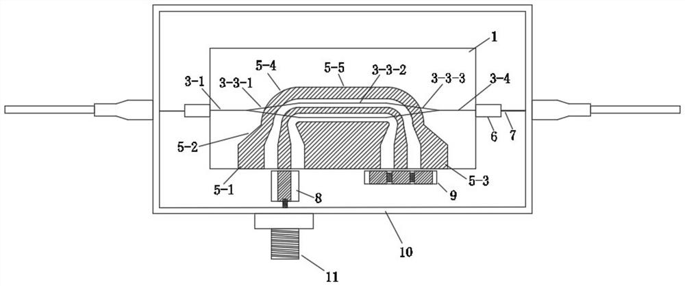
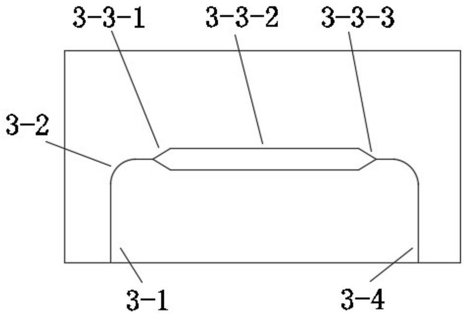
The invention discloses a lithium niobate film electro-optical modulator. The input end and the output end of a lithium niobate film optical waveguide are placed on the bottom edge of a lithium niobate film electro-optical modulator chip, and the input end and the output end of the lithium niobate film optical waveguide are respectively connected with a modulation area optical waveguide by adopting a 90-degree bent optical waveguide. Secondly, the coplanar traveling wave electrode in the modulation area is connected with the electrode input port or the electrode output port only through a section of transition electrode, and no 90-degree turning transition electrode exists. According to the innovative structure, on one hand, the input optical fiber and the output optical fiber can be placed at the bottom edge of the tube shell of the electro-optical modulator to further reduce the length of the electro-optical modulator, on the other hand, microwave signal loss caused by a 90-degree turning transition electrode in the traveling wave electrode can be reduced, and the modulation bandwidth of the electro-optical modulator can be improved.

Description

technical field [0001] The invention can be applied to technical fields such as optical fiber communication, optical fiber sensing, microwave photonics, quantum communication, etc., and specifically relates to a lithium niobate thin film electro-optical modulator. Background technique [0002] Optical modulators are widely used in optical fiber communication, optical fiber sensing, microwave photonics, quantum communication and other technical fields. A key function of optical fiber for low-loss transmission. The external modulator using the principle of linear electro-optic effect of lithium niobate crystal has an important application in optical fiber signal transmission system due to its outstanding advantages such as low chirp coefficient, high modulation bandwidth, and high on-off extinction ratio. [0003] The lithium niobate electro-optic modulator chip fabricated on the lithium niobate block material with traditional technical solutions has the advantages of good st...

Claims


Application Information

Patent Timeline
Patent Type & Authority Applications(China)
IPC IPC(8): G02F1/03
CPCG02F1/0311
Inventor 李萍
Owner 天津领芯科技发展有限公司
Learn More