Engine air intake system with air inlet flow guiding blade grid and simulated analysis method

A technology of air intake system and simulation analysis, which is applied in the direction of engine components, combustion engines, machines/engines, etc., can solve the problems of engine crankshaft acceptance imbalance, air intake imbalance, etc., and achieve a friendly working environment for the engine, rapid power output, and The effect of speeding up the response

Inactive Publication Date: 2021-05-28
HUBEI UNIV OF AUTOMOTIVE TECH
View PDF8 Cites 2 Cited by
  • Summary
  • Abstract
  • Description
  • Claims
  • Application Information

AI Technical Summary

Problems solved by technology

The existing air intake arrangement is generally a front air intake layout, such as figure 1 As shown, its disadvantages are: for the middle-mounted arrangement of the intake system of the three-cylinder engine, the airflow flows through the restrictor valve, enters the plenum chamber through the intake manifold, and then flows to the three intake manifolds. This layout will lead to the leftmost The air flow of the intake manifold one and the rightmost intake manifold three is less than the air flow of the middle intake manifold two
However, it cannot essentially solve the problem of unbalanced air intake, which will seriously lead to unbalanced intake of the engine crankshaft.

Method used


Image

  • Engine air intake system with air inlet flow guiding blade grid and simulated analysis method
  • Engine air intake system with air inlet flow guiding blade grid and simulated analysis method
  • Engine air intake system with air inlet flow guiding blade grid and simulated analysis method

Examples


Embodiment 2

[0054]The simulation analysis method of the engine air intake system with air intake guide leaves includes the following steps:

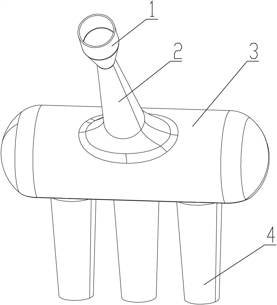
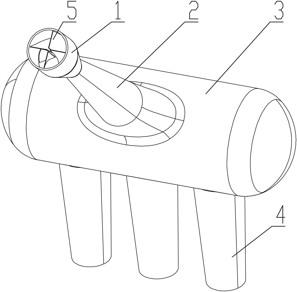
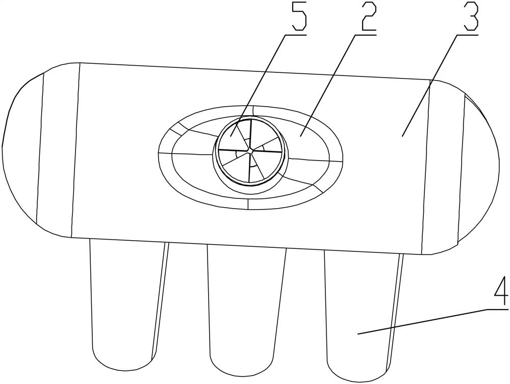
[0055] Step 1: Establish a three-dimensional model of the intake system;

[0056] Step 2: Import the 3D model into Fluent software;

[0057] Step 3: Structural grid division of the 3D model;

[0058] Step 4: Use Realizable's turbulent flow model to perform rotational flow simulation analysis, and set boundary conditions and initial conditions;

[0059] Step 5: Use the turbulence empirical value calculator to simulate and calculate the turbulence intensity at the inlet end and the turbulence intensity at the outlet end.

[0060] When performing structural grid division in the step 3, the QUICK format is adopted;

[0061] The discretization methods all use the second-order upwind model.

Embodiment 3

[0063] This embodiment mainly uses Fluent software to analyze the existing air intake system and the new air intake system, and compare the total air intake volume and air intake balance between the two. This analysis uses the Realizable k-ε turbulence model. For the convenience of comparison, the same boundary conditions and initial conditions are set before and after improvement. This embodiment adopts the boundary condition of constant pressure difference, the reference pressure is set to 101300Pa, the inlet pressure is 0Pa, and the outlet pressure is -10000Pa. The hydraulic diameter of the inlet end is 45mm, and the hydraulic diameter of the outlet section is 40.6mm. Using the turbulence k-ε empirical value calculator, the turbulence intensity at the inlet end is 3.75%, and the turbulence intensity at the outlet end is 3.9%. The QUICK format can provide higher computational accuracy when computing rotating flow problems with structured meshes, but in other cases the accur...


PUM


Abstract

The invention provides an engine air intake system with an air inlet flow guiding blade grid and a simulated analysis method. The system comprises a pressure stabilizing cavity, wherein an air inlet main pipe is connected to a middle position of one side of the top of the pressure stabilizing cavity, a current limiting valve is mounted at an inlet end of the air inlet main pipe, a plurality of air inlet manifolds are parallelly mounted on one side of the bottom of the pressure stabilizing cavity, and an air flow guiding sheet for guiding an inlet air flow and converting the same into a rotary flow is mounted in the inlet end of the current limiting valve or the air inlet main pipe. By additionally mounting the air flow guiding sheet based on the existing current limiting valve, an air flow entering the pressure stabilizing cavity from the air inlet main pipe is converted from a direct current into the rotary current, so that the air inlet air flow is higher in flow rate and the total air inlet amount is increased. The rotary flow entering the pressure stabilizing cavity can fill the pressure stabilizing cavity quickly, and thus, air flow amounts of the pressure stabilizing cavity entering the air inlet manifolds are more balanced, and a working environment of an engine is more environmental-friendly.

Description

technical field [0001] The invention belongs to the field of daily necessities, and in particular relates to an engine air intake system with an air intake guide vane and a simulation analysis method. Background technique [0002] The Formula Student China Contest (FSCC) stipulates that all airflow entering the engine must pass through a restrictor valve with a diameter of 20mm. Due to the function of the restrictor valve, the air intake into the engine is greatly reduced, which in turn affects the power and torque of the engine. According to the calibration of the bench, after adding the restrictor valve, the power and torque of the engine are lower than those of the original engine. reduced by around 30%. The air intake arrangement is generally divided into front air intake and side air intake. Although the front air intake will have a better air intake balance than the side air intake, the intake air volume of each intake manifold will still vary. There is a difference....

Claims


Application Information

Patent Timeline
Patent Type & Authority Applications(China)
IPC IPC(8): F02M35/10F02B29/02G06F30/20G06T17/00
CPCF02B29/02F02M35/10006F02M35/10091F02M35/10262G06T17/00G06F30/20Y02T10/12
Inventor 孙阳杨润泽
Owner HUBEI UNIV OF AUTOMOTIVE TECH
Why Eureka
Try Eureka