


Quick Research
Generate reliable direction feasibility study reports for your R&D in just a few steps.

Technical Q&A
Discover and master advanced knowledge NOW. Basics, ideas, possibilities, all at once.

Find Solutions
As an expert in R&D theories, this can generate solutions to your technical problems instantly.

Evaluate Feasibility
Analyze your overall solution with one click, know your potential R&D risks in advance.

Monitor Landscape
Get weekly tech updates, stay abreast of the latest tech innovations and key insights.
Lean-burn and rich-burn alternating type catalytic burner and operation method
A catalytic burner and catalytic combustion technology, applied in combustion methods, gas fuel burners, burners, etc., can solve the problems of catalyst carbon deposition, large catalyst consumption, complex components, etc. Combustion stability and wide range of fuel adaptability
- Summary
- Abstract
- Description
- Claims
- Application Information
AI Technical Summary
Problems solved by technology
Method used
Image


Examples
specific Embodiment 1
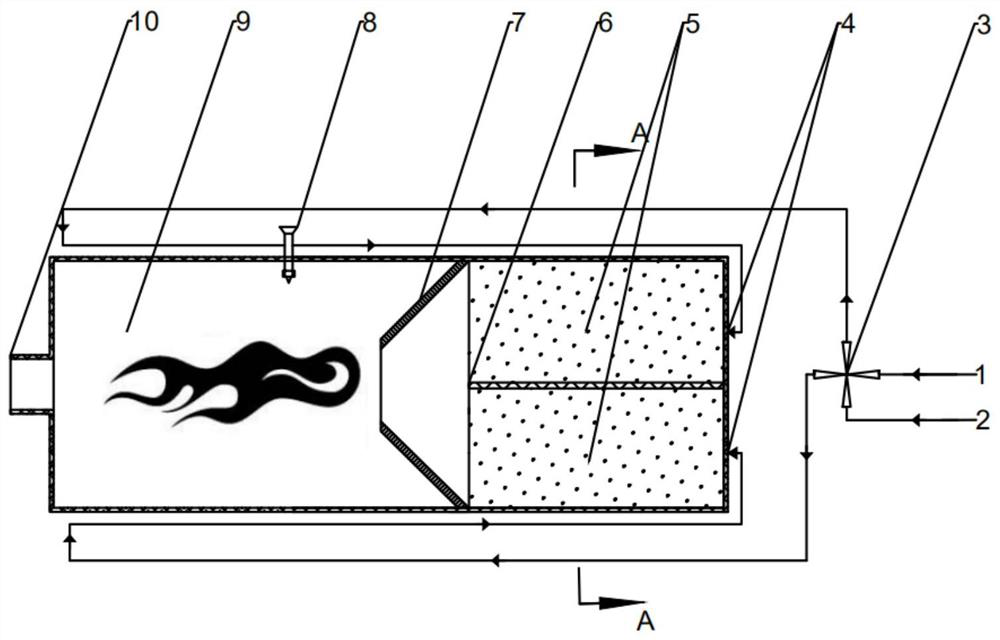
[0027] Equipment structure and composition: refer to figure 1 , the first gas channel 1 and the second gas channel 2 are connected with the four-way valve 3 to realize the switching of lean / rich premixed gas, the four-way valve 3 is respectively connected with two gas inlets 4 through the gas pipeline, and the gas inlet 4 Behind is the catalytic combustion zone 5 . The axial section of the burner is square, and a catalytic combustion zone 5 and a gas phase combustion zone 9 are coaxially arranged in sequence along the gas flow direction inside the burner body. The catalytic combustion zone 5 is divided into upper and lower independent parts by the partition plate 6 in the axial direction. The main geometric dimensions (flow area and volume) of the two parts are the same, and the catalyst parameters (type, loading capacity, air speed ratio parameters) same. A swirl vane 7 is arranged coaxially between the catalytic combustion zone 5 and the gas phase combustion zone 9 . An i...
specific Embodiment 2
[0030] Equipment structure and composition: refer to image 3 , the first gas channel 1 and the second gas channel 2 are connected with the four-way valve 3 to realize the switching of lean / rich premixed gas, the first gas channel and the end of B are connected with two gas inlets 4, behind the gas inlet 4 It is the catalytic combustion zone 5. The burner has a cylindrical hollow structure, and the gas phase combustion zone 9 is arranged in the middle of the burner body. The catalytic combustion zone 5 is divided into a rich-burn catalytic combustion zone and a lean-burn catalytic combustion zone, which are symmetrically arranged on both sides of the gas-phase combustion zone 9 . The main geometric dimensions (flow area and volume) of the rich-burn and lean-burn catalytic combustion zones are the same, and the catalyst parameters (type, loading, and space velocity ratio parameters) are the same. The gas inlet 4 is located at the center of the outer end faces of the catalytic ...
specific Embodiment 3
[0033] refer to figure 1, the first gas channel 1 and the second gas channel 2 are connected with the four-way valve 3 to realize the switching of lean / rich premixed gas, the first gas channel and the end of B are connected with two inner and outer nested gas inlets 4, The catalytic combustion zone 5 is immediately behind the gas inlet 4 . The burner is a cylindrical hollow structure, and a catalytic combustion zone 5 and a gas phase combustion zone 9 are coaxially arranged in sequence along the gas flow direction inside the burner body. The catalytic combustion zone 5 is divided into an inner catalytic combustion zone and an outer ring catalytic combustion zone. The main geometric dimensions (flow area and volume) of the inner and outer ring catalytic combustion zones are the same, and the catalyst parameters (type, loading, space velocity ratio parameters )same. A swirl vane 7 is arranged coaxially between the catalytic combustion zone 5 and the gas phase combustion zone 9...
PUM
 Abstract
Description
Claims
Application Information
 - R&D Engineer
- R&D Manager
- IP Professional
- Industry Leading Data Capabilities
- Powerful AI technology
- Patent DNA Extraction
Browse by: Latest US Patents, China's latest patents, Technical Efficacy Thesaurus, Application Domain, Technology Topic, Popular Technical Reports.
© 2024 PatSnap. All rights reserved.Legal|Privacy policy|Modern Slavery Act Transparency Statement|Sitemap|About US| Contact US: help@patsnap.com