Integrated optical fiber type photoacoustic probe capable of realizing lateral ultrasonic excitation and detection

A technology of ultrasonic excitation and photoacoustic probe, which is applied in measuring devices, material analysis through optical means, instruments, etc., can solve the problem of weak photoacoustic effect and achieve the effect of reducing weight and volume

Active Publication Date: 2021-05-28
BEIHANG UNIV
View PDF6 Cites 0 Cited by
  • Summary
  • Abstract
  • Description
  • Claims
  • Application Information

AI Technical Summary

Problems solved by technology

The probe with this structure directly irradiates the excitation light onto the target object after passing through the transparent film. Higher energy will cause thermal ablation of the target object, but for objects with a low light absorption coefficient, the photoacoustic effect will be very strong. weak

Method used


Image

  • Integrated optical fiber type photoacoustic probe capable of realizing lateral ultrasonic excitation and detection
  • Integrated optical fiber type photoacoustic probe capable of realizing lateral ultrasonic excitation and detection

Examples


Embodiment 1

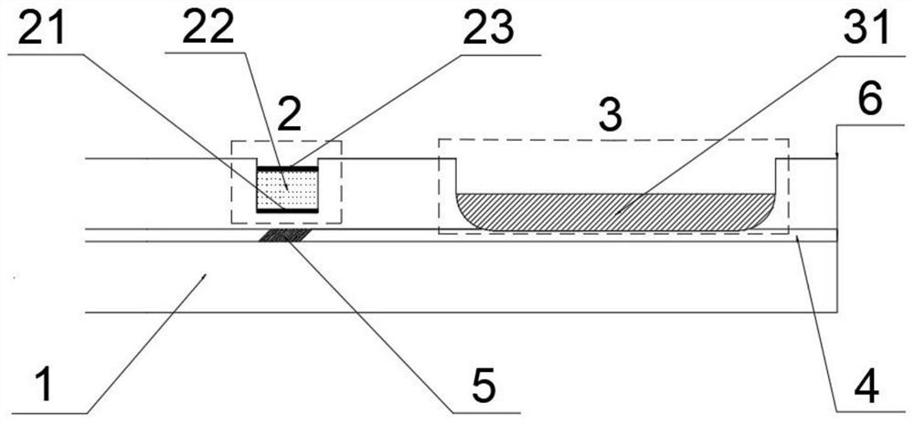
[0041] Embodiment 1, a group of typical components of fiber optic ultrasonic probes and their structural dimensions:

[0042] The model of the optical fiber (1) is Liekki passive 10 / 125DC optical fiber, the outer diameter of the cladding is 125 μm, and the diameter of the core is 10 μm.

[0043] The etched microcavity at the photoacoustic signal detection unit (2) has a width of 30 μm and a depth of 45 μm; the thickness of the F-P cavity structure is about 41.64 μm, the thickness of the dielectric mirrors (21) and (23) are both 1.82 μm, and the polymer film (22) The thickness is 38 μm, wherein the materials of the dielectric mirrors (21) and (23) are zinc sulfide and sodium hexafluoroaluminate, and an eight-layer structure is formed by alternate sputtering; the material of the F-P cavity polymer film (22) It is C-type parylene.

[0044] The polishing length of the photoacoustic signal excitation unit (3) is 10 mm, and the polishing depth is 59 μm; the photoacoustic material (...

Embodiment 2

[0047] Embodiment 2, a group of typical components of fiber optic ultrasonic probes and their structural dimensions:

[0048] The model of the optical fiber (1) is Liekki passive 10 / 125DC optical fiber, the outer diameter of the cladding is 125 μm, and the diameter of the core is 10 μm.

[0049] The etched microcavity at the photoacoustic signal detection unit (2) has a width of 30 μm and a depth of 45 μm; the thickness of the F-P structure is about 41.5 μm, the thickness of the dielectric mirrors (21) and (23) are both 1.75 μm, and the polymer film ( 22) The thickness is 38 μm, wherein the materials of the dielectric mirrors (21) and (23) are magnesium fluoride and zinc selenide, and an eight-layer structure is formed by alternate sputtering; the material of the F-P cavity polymer film (22) is poly Polyethylene terephthalate (PET) or UV-curable optical glue.

[0050] The polishing length of the photoacoustic signal excitation unit (3) is 10 mm, and the polishing depth is 59 ...


PUM

PropertyMeasurementUnit
thicknessaaaaaaaaaa
thicknessaaaaaaaaaa
diameteraaaaaaaaaa

Abstract

The invention discloses an integrated optical fiber type photoacoustic probe capable of lateral ultrasonic excitation and detection. The side wall of an optical fiber (1) in the probe is polished and ground, and a photoacoustic material (31) is deposited on the side wall to form a photoacoustic signal excitation unit (3) to excite a photoacoustic signal; a Fabry-Perot (F-P) interference cavity is manufactured through femtosecond laser etching, and an F-P cavity type photoacoustic signal detection unit (2) composed of a dielectric mirror (21), a polymer film (22) and a dielectric mirror (23) is formed and used for detecting photoacoustic signals; and a 45-degree inclined grating (5) is manufactured on the optical fiber core (4) and is used for separating excitation light from detection light. Due to the filtering effect of the oblique grating (5), the excitation light beam transmitted in the optical fiber (1) is transmitted to the photoacoustic signal excitation unit (3) near the optical fiber end (6) through the oblique grating (5), and the deposited photoacoustic material (31) excites an ultrasonic signal under the photoacoustic effect; and the detection light beam is reflected to the F-P interference cavity on the side surface of the optical fiber through the inclined grating so as to detect a photoacoustic signal.

Description

technical field [0001] The invention belongs to the technical field of optical fiber sensing, in particular to an integrated optical fiber photoacoustic probe capable of lateral ultrasonic excitation and detection. Background technique [0002] In 1880, Bell discovered that objects emit acoustic signals when illuminated by a periodic light source (BELL A G. Upon the production and reproduction of sound by light [J]. Journal of the Society of Telegraph Engineers, 1880, 9(34): 404–426. ), this phenomenon is called the photoacoustic effect. That is, when light is irradiated on an object, the object absorbs light energy and converts it into heat energy, and the volume expands; when a pulsed light source or a modulated light source is used, the rise and fall of the object's temperature will cause the volume to expand and contract, so that sound waves can be radiated outward. Traditional ultrasonic transducers are mostly made of piezoelectric crystals based on the piezoelectric e...

Claims


Application Information

Patent Timeline
Patent Type & Authority Applications(China)
IPC IPC(8): G01N21/17
CPCG01N21/1702G01N2021/1706
Inventor 李成卢杉杉刘健
Owner BEIHANG UNIV
Why Eureka
Try Eureka