Nitrogen oxide treatment system and treatment method thereof

A technology for nitrogen oxides and treatment systems, applied in chemical instruments and methods, separation methods, gas treatment, etc., can solve problems such as poor treatment effect and induced deactivation, so as to avoid catalyst poisoning, slow down gas flow rate, and increase reduction efficiency effect

Active Publication Date: 2021-06-01
CHENGDU TECHCAL UNIV
View PDF7 Cites 2 Cited by
  • Summary
  • Abstract
  • Description
  • Claims
  • Application Information

AI Technical Summary

Problems solved by technology

At present, the selective catalytic reduction of NOx with ammonia is considered to be the most effective measure to reduce NOx emissions, but ordinary catalysts are easily destroyed by SO 2 Induced inactivation, resulting in poor treatment

Method used


Image

  • Nitrogen oxide treatment system and treatment method thereof

Examples


Embodiment

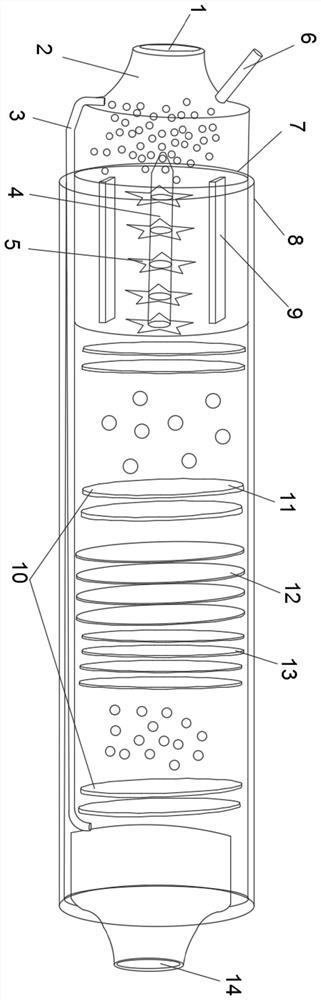
[0037] A preferred embodiment of the present invention provides a nitrogen oxide treatment system, including a gas mixing adjustment area, a plasma excitation area, a SO 2 Absorption zone and NO X Reduction zone, plasma excitation zone, SO 2 Absorption zone and NO X The outer jacket of the reduction area is provided with an insulating and heat-insulating shell 8, and the gas mixing adjustment area is provided with an air inlet 1, and the NO X The reduction zone is provided with an exhaust port 14;

[0038] The gas mixing adjustment area is provided with a gas flow rate adjustment pipe 2 for adjusting the air intake flow rate of the air inlet 1, and the gas mixing adjustment area is also connected with an air intake pipe 6;

[0039] An insulating tube 7 is sleeved in the plasma excitation area, and a discharge copper plate 9 is relatively arranged in the insulating tube 7, and a porous drying plate 10 is detachably arranged behind the area where the insulating tube is locate...

experiment example 1

[0058] Exhaust gas volume is 600Nm 3 / H, the gas composition is: O 2 =18.31kg / H, NOx=231.7kg / H, CO 2 =56.86kg / h, SO 2 =12.35kg / h, the rest is N 2 . The waste gas is passed into the device of the embodiment of the present invention, and treated according to the method of the embodiment, and the NOx in the tail gas at the exhaust port is 4.5g / h.

experiment example 2

[0060] The exhaust gas volume is 580Nm 3 / H, the gas composition is: O 2 =12.55kg / H, NOx=187.6kg / H, CO 2 =44.98kg / h, SO 2 =17.34kg / h, the rest is N 2 . The exhaust gas is passed into the device of the embodiment of the present invention, and treated according to the method of the embodiment, and the NOx in the tail gas at the exhaust port is 3.8g / h.


PUM


Abstract

The invention discloses a nitrogen oxide treatment system and a method thereof, the nitrogen oxide treatment system comprises a gas mixing adjusting area, a plasma excitation area, an SO2 absorption area and an NOX reduction area which are communicated in sequence, the plasma excitation area, the SO2 absorption area and the NOX reduction area are sleeved with an insulating and heat-insulating shell, the gas mixing adjusting area is provided with a gas inlet, and the NOX reduction area is provided with a gas outlet; a gas flow rate adjusting pipe for adjusting the gas inlet flow rate of the gas inlet is arranged in the gas mixing adjusting area, and the gas mixing adjusting area is further communicated with a gas inlet pipe; an insulating tube is sleeved in the plasma excitation area, discharge copper plates are oppositely arranged in the insulating tube, and a porous drying plate is detachably arranged behind the area where the insulating tube is located; a porous absorption plate is arranged in the SO2 absorption area; a porous first catalytic reaction plate, a porous second catalytic reaction plate and a porous drying plate are sequentially arranged in the NOX reduction area. According to the treatment device and the treatment method thereof, nitrogen oxides can be efficiently treated, and SO2 poisoning and inactivation are not prone to occurring.

Description

technical field [0001] The invention belongs to the technical field of nitrogen oxide treatment equipment, and in particular relates to a nitrogen oxide treatment system and treatment method. Background technique [0002] Nitrogen oxides refer to compounds composed only of nitrogen and oxygen, including a variety of compounds, such as nitrous oxide (N 2 O), nitric oxide (NO), nitrogen dioxide (NO 2 ), nitrogen trioxide (N 2 o 3 ), dinitrogen tetroxide (N 2 o 4 ) and dinitrogen pentoxide (N 2 o 5 )Wait. Except for nitrous oxide and nitrogen dioxide, other nitrogen oxides are unstable, and turn into nitrogen dioxide and nitrogen monoxide when exposed to light, humidity or heat, and nitrogen monoxide turns into nitrogen dioxide. Nitrogen oxides are toxic to varying degrees. Nitrogen oxides combined with water in the air are eventually converted to nitric acid and nitrates, which are removed from the air with precipitation and dustfall. Nitric acid is one of the causes...

Claims


Application Information

Patent Timeline
Patent Type & Authority Applications(China)
IPC IPC(8): B01D53/32B01D53/18B01D53/14B01D53/56B01D53/86B01D53/26B01D53/75
CPCB01D53/32B01D53/18B01D53/1481B01D53/56B01D53/8628B01D53/26B01D53/75B01D2259/818B01D2251/2062B01D2258/02
Inventor 景江范天斌何若雪彭靖张欣王卓何思雨黄树白世星纪福林
Owner CHENGDU TECHCAL UNIV
Why Eureka
Try Eureka