Microwave and millimeter wave coplanar common-caliber antenna based on embedded structure

A millimeter-wave and common-aperture technology, which is applied to antenna arrays, antennas, and resonant antennas that are energized separately, can solve the problems of narrow bandwidth, high integration, and impossibility of high- and low-frequency antennas, and achieve small beam scanning and high integration , high efficiency effect

Active Publication Date: 2021-06-01
NANTONG UNIVERSITY
View PDF5 Cites 1 Cited by
  • Summary
  • Abstract
  • Description
  • Claims
  • Application Information

AI Technical Summary

Problems solved by technology

At present, there are mainly four ways to realize the common aperture of antennas. The first is to place two antennas with different frequencies adjacent to each other. This form of common aperture antenna has low space utilization efficiency; The stacked placement of low-frequency antennas has a high cross-section, and often there is an air layer in the middle of the antenna structure, which makes it impossible to achieve a high degree of integration; the third type is a microwave / millimeter wave common-aperture antenna based on a mode composite structure , this type of antenna is more suitable for end-fire antenna design. If it is used for side-fire antenna design, it often has the problem of narrow bandwidth of high and low frequency antennas; the fourth is the embedded structure, which has excellent high and low frequency independent design ability and great application potential
However, the above-mentioned microwave / millimeter wave co-aperture technologies currently have a common defect, that is, the co-aperture integration of the side-firing microwave antenna and the millimeter-wave beam scanning array cannot be realized, so it is difficult to solve the application of terminal equipment to the side-firing antenna need

Method used


Image

  • Microwave and millimeter wave coplanar common-caliber antenna based on embedded structure
  • Microwave and millimeter wave coplanar common-caliber antenna based on embedded structure
  • Microwave and millimeter wave coplanar common-caliber antenna based on embedded structure

Examples


Embodiment 1

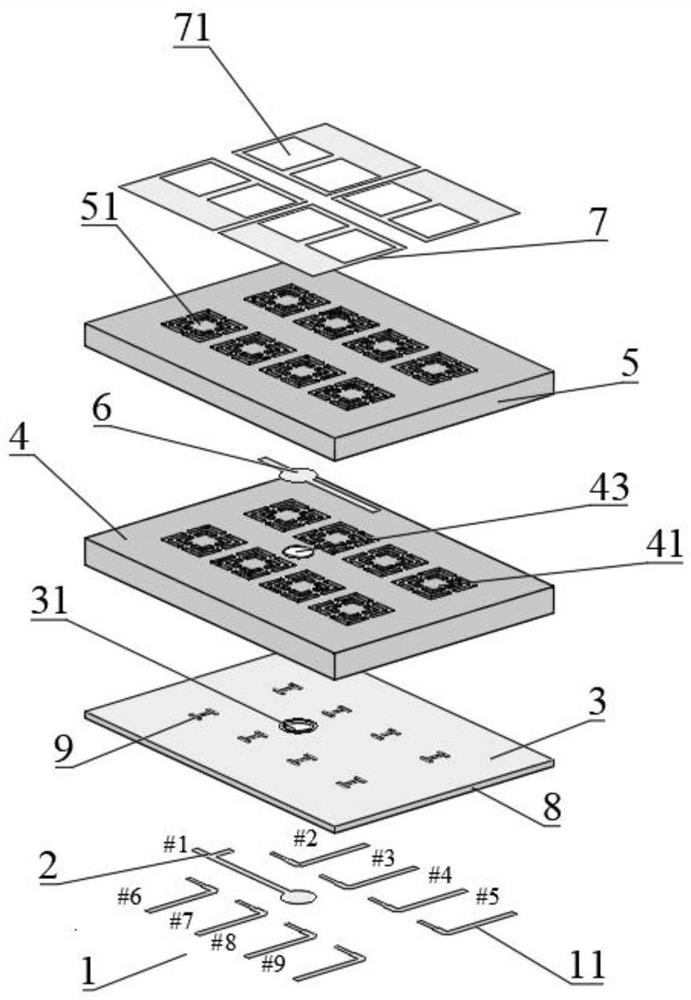
[0043] The dielectric constant of the third substrate used in this case is 3.38, the loss angle is 0.0027, and the thickness is 0.305mm. The dielectric constant of the first substrate and the second substrate are 6.15, the loss angle is 0.0019, and the thicknesses are 1.016mm and 1.27mm respectively. mm. Overall profile height 2.591mm (~0.03λ 0 @3.5GHz), plane size 35.5mm×26mm (~0.4×0.3λ 0 2 @3.5GHz).

[0044] The transmission response and radiation response of the antenna are as Figure 4~5 As shown, for S11≤-10dB, the bandwidth range is 3.3-3.7GHz, 24.5-27.8GHz, it can be seen that the China Telecom frequency band (3.4-3.5GHz) and China Unicom frequency band (3.5-3.6GHz) in 5G are well covered And China's 5G millimeter wave test frequency band (24.75-27.5GHz), the in-band gains are 5dBi and 15dBi respectively.

[0045] Such as Figure 6 As shown, the pattern of the antenna is symmetrical, and the cross-polarization is better than 20dB. Such as Figure 7 As shown, the...


PUM

PropertyMeasurementUnit
thicknessaaaaaaaaaa
thicknessaaaaaaaaaa
dielectric lossaaaaaaaaaa

Abstract

The invention provides a microwave and millimeter wave coplanar common-caliber antenna based on an embedded structure. The antenna comprises a high-frequency feed microstrip structure, a low-frequency feed microstrip structure, a metal ground, a first metallization groove formed in a second substrate, a second metallization groove formed in the third substrate, and a feed metal strip arranged on the second substrate and positioned between the two rows of first metallization grooves; the feed metal strip is connected with the low-frequency feed microstrip structure through a first metal through hole formed in the second substrate, a first round hole formed in the metal ground and a second metal through hole formed in the first substrate in sequence and is not in contact with the metal ground; and the antenna also includes an antenna radiation patch. According to the microwave and millimeter wave coplanar common-caliber antenna based on the embedded structure, the millimeter wave dielectric resonator antenna array is embedded into the microwave antenna array, the edge-emitting microwave / millimeter wave coplanar common-caliber antenna is achieved, the whole antenna can be machined through a PCB technology, and the integration level is high.

Description

technical field [0001] The invention relates to the technical field of microwave and millimeter wave communication, in particular to a microwave and millimeter wave coplanar and co-aperture antenna based on an embedded structure. Background technique [0002] With the rapid development of 5G technology, the increase in the number of frequency bands and the improvement of performance indicators have brought unprecedented design challenges to wireless terminal equipment that is highly pursuing miniaturization and thinning. As far as the terminal antenna is concerned, it is faced with the obvious problem of how to design and integrate the newly added microwave band antenna and the millimeter wave band antenna array in the already very limited space. Among them, the microwave antenna must realize broadband or The dual-band has an extremely low profile height to meet the needs of thinner and lighter equipment. In order to overcome the high transmission loss, the millimeter-wave ...

Claims


Application Information

Patent Timeline
Patent Type & Authority Applications(China)
IPC IPC(8): H01Q1/38H01Q1/00H01Q21/06H01Q21/00H01Q9/04
CPCH01Q1/38H01Q1/002H01Q21/06H01Q21/065H01Q21/0006H01Q9/0485
Inventor 杨汶汶丁鑫浩陈建新
Owner NANTONG UNIVERSITY
Why Eureka
Try Eureka