


Quick Research
Generate reliable direction feasibility study reports for your R&D in just a few steps.

Technical Q&A
Discover and master advanced knowledge NOW. Basics, ideas, possibilities, all at once.

Find Solutions
As an expert in R&D theories, this can generate solutions to your technical problems instantly.

Evaluate Feasibility
Analyze your overall solution with one click, know your potential R&D risks in advance.

Monitor Landscape
Get weekly tech updates, stay abreast of the latest tech innovations and key insights.
Secondary side synchronous rectification circuit with thermal protection function, and electronic equipment
A technology of synchronous rectification and thermal protection, applied in emergency protection circuit devices, electrical components, output power conversion devices, etc., can solve problems such as thermal breakdown of power tubes, large conduction voltage drop, unstable working system, etc., to achieve Realize the effect of thermal protection and constant temperature work
- Summary
- Abstract
- Description
- Claims
- Application Information
AI Technical Summary
Problems solved by technology
Method used
Image

Examples
Embodiment 1
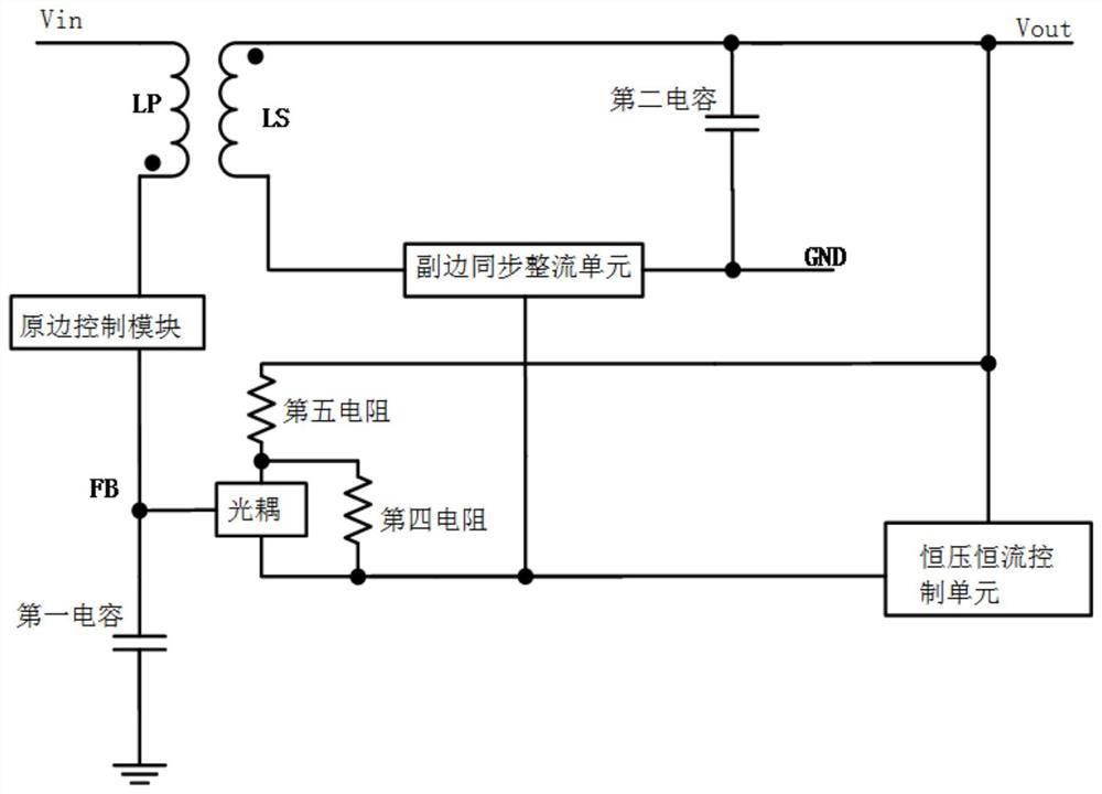
[0084] Please refer to figure 1 , a secondary-side synchronous rectification circuit with thermal protection, including a primary-side control module, an optocoupler, a synchronous rectification control unit, a temperature detection unit, a transformer, a power tube, and a constant voltage and constant current control unit;
[0085] The primary side control module is used to control the input power of the primary side (LP) of the transformer, and the constant voltage and constant current control unit is used to control the feedback amount of the optocoupler, specifically:
[0086] The output end of the primary side control module is connected to the primary side of the transformer, specifically the output end of the primary side control module is connected to the LP of the transformer, and the other end of the LP of the transformer is connected to the high voltage input end;
[0087] The output end of the temperature detection unit and the output end of the constant voltage an...
Embodiment 2
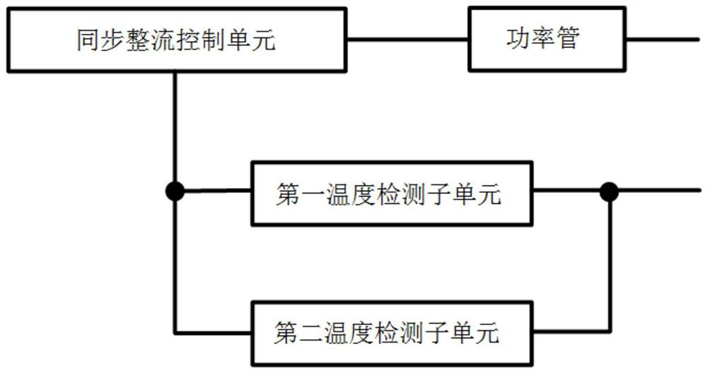
[0095] The difference between this embodiment and the first embodiment is that the power tube is sealed and applied with the synchronous rectification control unit and the temperature detection unit;
[0096] Specifically, please refer to figure 2 , the temperature detection unit includes a first temperature detection subunit and a second temperature detection subunit; the input end of the first temperature detection subunit and the input end of the second temperature detection subunit are respectively connected to the synchronous rectification The first output end of the control unit is connected, and the output end of the first temperature detection subunit and the output end of the second temperature detection subunit are respectively connected to the first end of the emission side of the optocoupler;
[0097] The first temperature detection subunit and the second temperature detection subunit correspond to different temperature thresholds, specifically:
[0098] Please r...
Embodiment 3
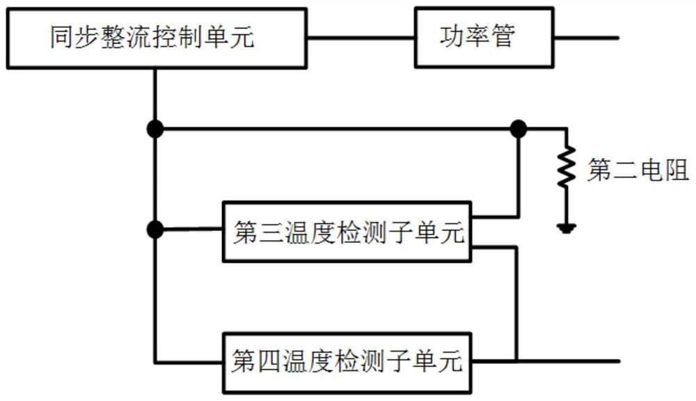
[0105] The difference between this embodiment and Embodiment 1 and Embodiment 2 is that the power tube is packaged separately, and the synchronous rectification control unit and the temperature detection unit are packaged together for application;
[0106] Please refer to image 3 , the temperature detection unit includes a third temperature detection subunit and a fourth temperature detection subunit; the secondary synchronous rectification circuit also includes a second resistor; the first input terminal of the third temperature detection subunit is connected to the One end of the second resistor is respectively connected to the first output end of the synchronous rectification control unit, and the output end of the third temperature detection subunit is connected to the first end of the emitting side of the optocoupler; the third temperature The second input end of the detection subunit is connected to the first output end of the synchronous rectification control unit; the...
PUM
 Abstract
Description
Claims
Application Information
 - R&D Engineer
- R&D Manager
- IP Professional
- Industry Leading Data Capabilities
- Powerful AI technology
- Patent DNA Extraction
Browse by: Latest US Patents, China's latest patents, Technical Efficacy Thesaurus, Application Domain, Technology Topic, Popular Technical Reports.
© 2024 PatSnap. All rights reserved.Legal|Privacy policy|Modern Slavery Act Transparency Statement|Sitemap|About US| Contact US: help@patsnap.com