Broadband gap waveguide array antenna

A technology of gap waveguide and array antenna, applied in the direction of antenna, antenna array, antenna components, etc., can solve the problems of low sidelobe, antenna cost increase, gain reduction, etc., achieve low sidelobe, optimize the pattern, and suppress cross poles effect

Active Publication Date: 2021-06-04
NINGBO UNIV
View PDF13 Cites 1 Cited by
  • Summary
  • Abstract
  • Description
  • Claims
  • Application Information

AI Technical Summary

Problems solved by technology

The traditional array antenna mainly includes a feed layer and a radiation layer. At present, there are two main solutions to reduce its side lobes. The first solution is to adjust the energy distribution of the radiation layer by adjusting the power distribution ratio of the feed layer to reduce the side lobes. However, this solution will always cause the main lobe to widen and the gain will decrease while reducing the side lobes. It cannot guarantee a narrow main lobe and obtain extremely low side lobes without sacrificing the gain; the second solution is to add poles above the radiation layer Adding a polarization layer can reduce the sidelobe, and increasing the polarization layer can rotate the electric field polarization direction of the radiation layer, and can optimize the E-plane and H-plane patterns of the antenna to achieve low sidelobes, but increasing the polarization layer in mass production will Increase the cost of the antenna by 20%
[0004] However, in the millimeter wave frequency band, more serious sidewall wave effects, higher dielectric loss and other unfavorable factors also bring troubles to the traditional array antenna design
The usability of traditional waveguide transmission lines is greatly reduced, so there is a need to find waveguide transmission lines with good performance in the mmWave frequency band

Method used


Image

  • Broadband gap waveguide array antenna
  • Broadband gap waveguide array antenna
  • Broadband gap waveguide array antenna

Examples


Embodiment

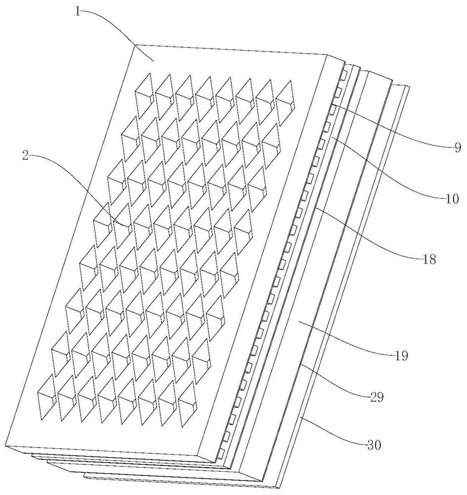
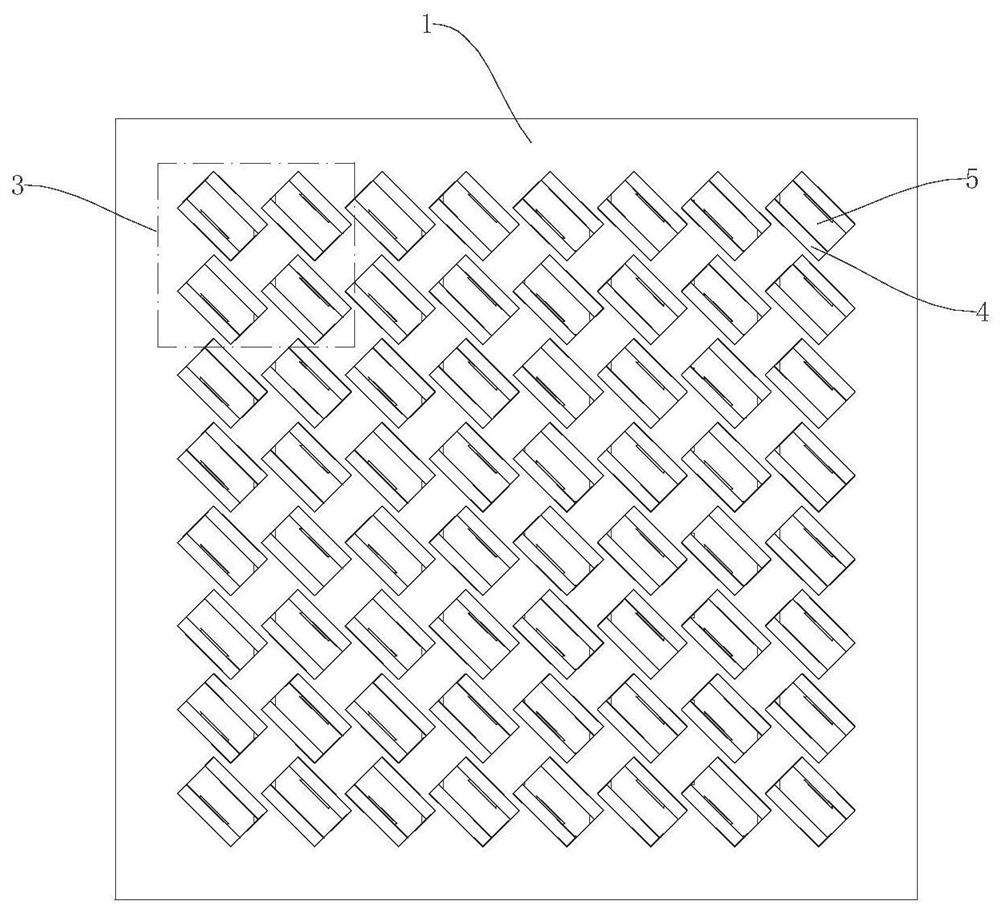
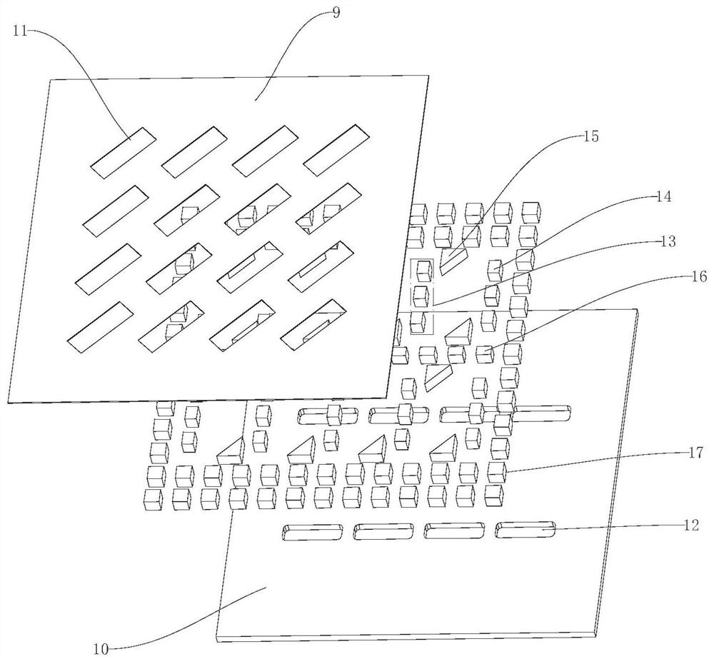
[0030] Example: such as figure 1 and figure 2 As shown, a wide-band gap waveguide array antenna includes a radiation layer and a feed layer stacked in order from top to bottom. The feed layer is used to convert a single TE10 mode into multiple TE10 modes with the same power and phase signal, and transmit multiple TE10 mode signals to the radiation layer, the radiation layer is used to radiate the multiple TE10 mode signals from the feed layer to free space, and the radiation layer includes radiation unit sub-arrays arranged in order from top to bottom layer, the first gap waveguide coupling layer and the second gap waveguide coupling layer, the radiation unit sub-array layer includes a first flat plate 1 and a radiation array 2 arranged on the first flat plate 1, the first flat plate 1 is a rectangular plate, and the radiation array 2 It is formed by distributing 16 radiating units 3 in a manner of 4 rows×4 columns, and each radiating unit 3 respectively includes a first rec...


PUM


Abstract

A broadband gap waveguide array antenna disclosed by the present invention comprises a radiation layer and a feed layer. The radiation layer comprises a radiation unit sub-array layer, a first gap waveguide coupling layer and a second gap waveguide coupling layer, and the radiation unit sub-array layer comprises a first flat plate and a radiation array arranged on the first flat plate. The radiation array is formed by distributing 16 radiation units according to a mode of 4 rows * 4 columns, each radiation unit comprises a first rectangular cavity and a second rectangular cavity which are stacked from top to bottom, and a first air cavity which equally divides energy into two paths is arranged in the first gap waveguide coupling layer; the second gap waveguide coupling layer is internally provided with a second air cavity for dividing energy into four paths; the feed layer is provided with a third air cavity for uniformly dividing the energy into two paths of energy with consistent amplitude and phase and respectively sending the two paths of energy into the second gap waveguide coupling layer; on the basis of low side lobe, the antenna has the advantages of relatively high gain and efficiency and relatively low processing cost.

Description

technical field [0001] The invention relates to an array antenna, in particular to a wide-band gap waveguide array antenna. Background technique [0002] On the electromagnetic spectrum, the low-frequency spectrum is already quite crowded, and it is more and more urgent to carry out research on related technologies in higher frequency bands, such as millimeter wave frequency bands. The available frequency bandwidth and short electromagnetic wavelength of the millimeter wave frequency band have many advantages in designing antennas in this frequency band, such as easy realization of wider operating bandwidth and miniaturized design. [0003] With the improvement of radar anti-jamming requirements and the development of modern electronic industry, it is required that the antenna should have low sidelobe or extremely low sidelobe performance. The traditional array antenna mainly includes a feed layer and a radiation layer. At present, there are two main solutions to reduce its...

Claims


Application Information

Patent Timeline
Patent Type & Authority Applications(China)
IPC IPC(8): H01Q21/06H01Q21/00H01Q15/24H01Q1/36H01Q1/00
CPCH01Q21/061H01Q21/0006H01Q15/242H01Q1/36H01Q1/002
Inventor 张玲陆云龙尤阳朱其昂黄季甫
Owner NINGBO UNIV
Why Eureka
Try Eureka