

Clamping auxiliary forming device for two sides of molten pool in additive manufacturing process and method
A technology for additive manufacturing and molten pool, which is applied in the field of auxiliary forming devices for clamping both sides of the molten pool in the process of additive manufacturing, which can solve problems such as difficult application of width and size, and achieve the effect of improving dimensional accuracy.
- Summary
- Abstract
- Description
- Claims
- Application Information
AI Technical Summary
Problems solved by technology
Method used
Image

Examples
Embodiment 1
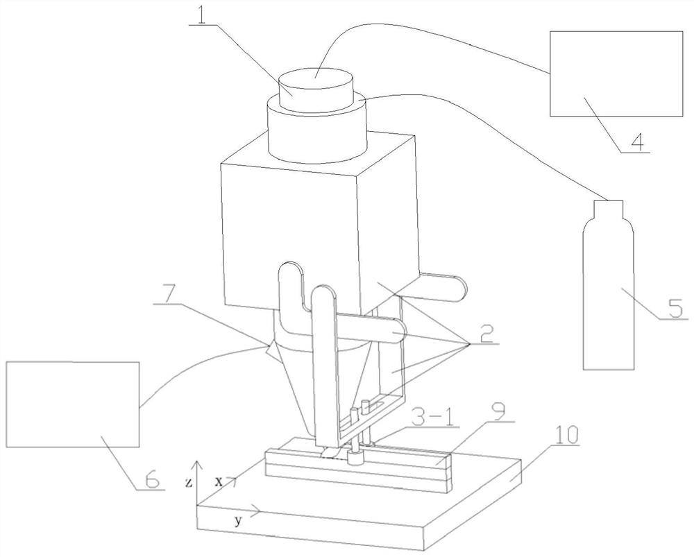
[0040] Take the unidirectional scanning method to manufacture a 316L stainless steel thin-walled part with a deposition layer width of 2mm as an example, such as figure 1 As shown, the coaxial powder feeding method is adopted, the heat source of laser deposition manufacturing is FCL-2000 semiconductor laser, and the GP-180 teaching robot is used to drive the laser deposition head to move, and the clamping parts are rollers. The specific steps are as follows:
[0041] Step 1: Polish the surface of the 316L stainless steel substrate with sandpaper to remove oil and impurities on the surface, and use absorbent cotton to soak in absolute ethanol, scrub the polished surface and wait for it to dry naturally, then place the substrate on the surface of the workbench. Sieve 316L powder in advance, place it in a vacuum drying oven, and dry it at 120°C for more than 2 hours, then place it in the powder feeder, turn on the power of the powder feeder and set its speed to 1.2 rpm. Set the p...
Embodiment 2
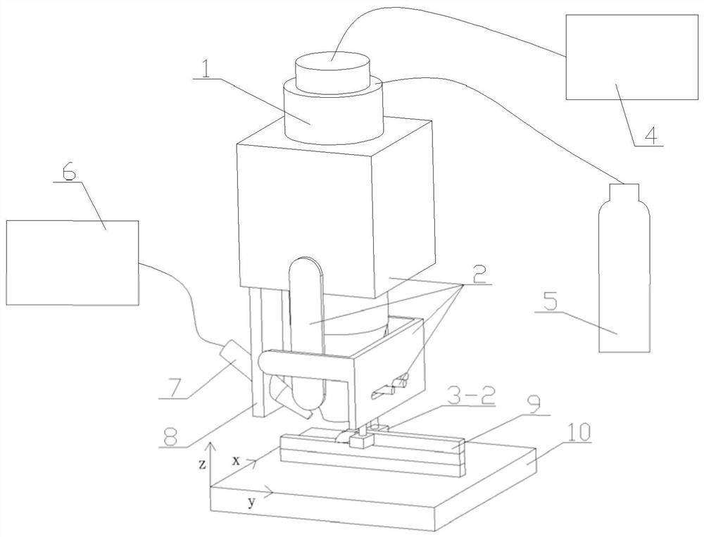
[0047] Take the unidirectional scanning method to manufacture TC4 thin-walled parts with a deposition layer width of 5mm as an example, such as figure 2 As shown, the heat source of laser deposition manufacturing is FCL-2000 fiber laser by means of coaxial shielding gas and lateral wire feeding, and the teaching manipulator GP-180 is controlled by the YRC-1000 control cabinet to drive the laser deposition head to move. The holding part is a clamping block, which specifically includes the following steps:
[0048] Step 1: Polish the surface of the TC4 substrate with sandpaper to remove surface attachments, and use absorbent cotton to soak in absolute ethanol, scrub the polished surface, and let it dry naturally. Place the substrate on the bench surface. Put the TC4 wire into the wire feeding device, turn on the power of the device and set the wire feeding speed to 200mm / min. Set the laser shielding gas flow rate to 8L / min. Turn on the laser and the water cooler, and set the...
PUM
 Abstract
Description
Claims
Application Information