Acoustic fluid micro pump based on micro electro mechanical technology

A micro-electromechanical and micro-pump technology, applied in the direction of pumps, mechanical equipment, machines/engines, etc., can solve the problems of limited application, additional products, unsustainability, etc., to achieve a wide range of applications, overcome complex structures, and efficiently pump Effect

Active Publication Date: 2021-06-15
TIANJIN UNIV
View PDF7 Cites 1 Cited by
  • Summary
  • Abstract
  • Description
  • Claims
  • Application Information

AI Technical Summary

Problems solved by technology

However, this kind of acoustic fluid pump cannot realize the effective conversion of electric energy-acoustic energy-kinetic energy, and the pumping flow rate is less than 50nL/min under the input power of 6W, the power consumption is high, and the overall miniaturization is difficult
[0005] In summary, mechanical micropumps have a relatively complex geometric structure, which hinders their size and manufacturing progress and limits their applications...

Method used


Image

  • Acoustic fluid micro pump based on micro electro mechanical technology
  • Acoustic fluid micro pump based on micro electro mechanical technology

Examples


Embodiment 1

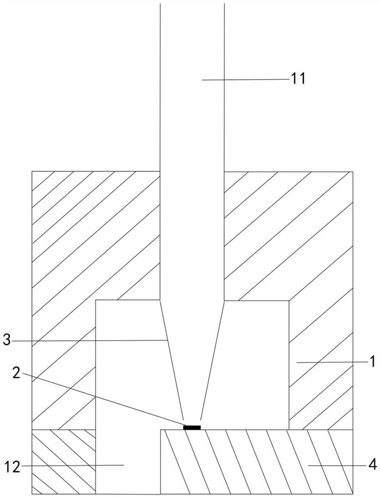
[0027] The present invention provides an acoustic fluid micropump based on microelectromechanical technology, including:

[0028] The pump chamber can be used for sample fixation and storage. There is an opening on the top of the cavity for a hard pipe to be inserted as an outlet, and an opening at the bottom of the cavity can be used as an inlet.

[0029] The resonator is arranged at the bottom of the pump cavity, can be connected with an external signal generator through a circuit board, and has a GHz-level resonance frequency.

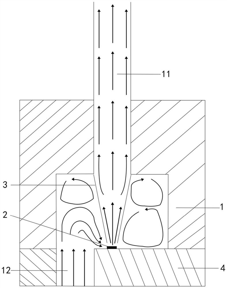
[0030] The pipe is a two-dimensional axisymmetric thin-walled pipe, the top of which is connected to the outlet. When the driven liquid in the pipe is working, the force on the part in contact with the inner wall of the pipe hinders its upward propagation, which is easy to cause backflow And reduce the back pressure, so the inner diameter below the pipe can be gradually reduced to reduce the loss of body force, suppress backflow, increase the back ...

Embodiment 2

[0035] In order to make the miniaturization and simplification of the present invention more prominent, the inventor made further improvements on the basis of Embodiment 1.

[0036] The resonator can be connected to the micro-miniature antenna through the circuit board, and the resonator can be driven to work by means of wireless power supply, which can realize the same function as the first embodiment, and can get rid of the shackles of wired connection, making it a portable portable micro-pump , the scope of application is wider and unrestricted.

[0037] The invention combines a GHz solid-package bulk acoustic wave resonator with a cavity with an intercepting pipeline to realize efficient pumping of liquid, and provides an acoustic fluid micropump based on microelectromechanical technology. The three-dimensional size of the pump body of the micropump is about 10 mm, which has the advantage of miniaturization; and there are no mechanical structures such as valves and membran...


PUM


Abstract

The invention discloses an acoustic fluid micro pump based on a micro electro mechanical technology. The pump comprises a pump cavity with an inlet and an outlet; a GHz-level resonator is arranged in the pump cavity; and a pipeline which extends from the outlet to the resonator and is not in contact with the resonator is arranged. According to the pump, the GHz-level resonator and the non-contact pipeline over the resonator are arranged in the pump cavity, the power amplifier and the signal generator are externally connected, stable and rapid one-way acoustic jet can be obtained, and efficient and continuous pumping of liquid is achieved. The pump has the advantages of miniature size, simple structure, low power consumption, wide application, compatibility with a semiconductor process, portability through a wireless driving mode and the like.

Description

technical field [0001] The invention relates to the field of microelectronic devices, in particular to an acoustic fluid micropump based on microelectromechanical technology. Background technique [0002] As the main driving component of microfluidic systems, micropumps have attracted the attention and research of many researchers since they were proposed, and have been widely used in different fields such as biomedicine, biochemical sensing, drug delivery, drug development, and fuel cells. The existing active micropumps can be roughly divided into two categories: mechanical micropumps and non-mechanical micropumps. Mechanical micropumps drive fluid flow through the displacement of moving parts. Common working principles include piezoelectric drive, thermal drive, electrostatic drive, phase change drive, electromagnetic drive, and some special shaped materials. Non-mechanical micropumps pump fluid by converting non-mechanical energy into liquid kinetic energy. Common workin...

Claims


Application Information

Patent Timeline
IPC IPC(8): F04B19/00
CPCF04B19/006
Inventor 段学欣游睿
Owner TIANJIN UNIV
Why Eureka
Try Eureka