Supergravity oxidation machine and tail gas treatment device and process
A technology of super-gravity oxidation and super-gravity machine, which is applied in the field of desulfurization, can solve the problems of high investment and operating costs, such as the high proportion of Claus devices, and achieve the effect of improving full contact
- Summary
- Abstract
- Description
- Claims
- Application Information
AI Technical Summary
Problems solved by technology
Method used
Image
Examples
Embodiment 1
[0051] Example 1 Ultra-gravity oxidizer
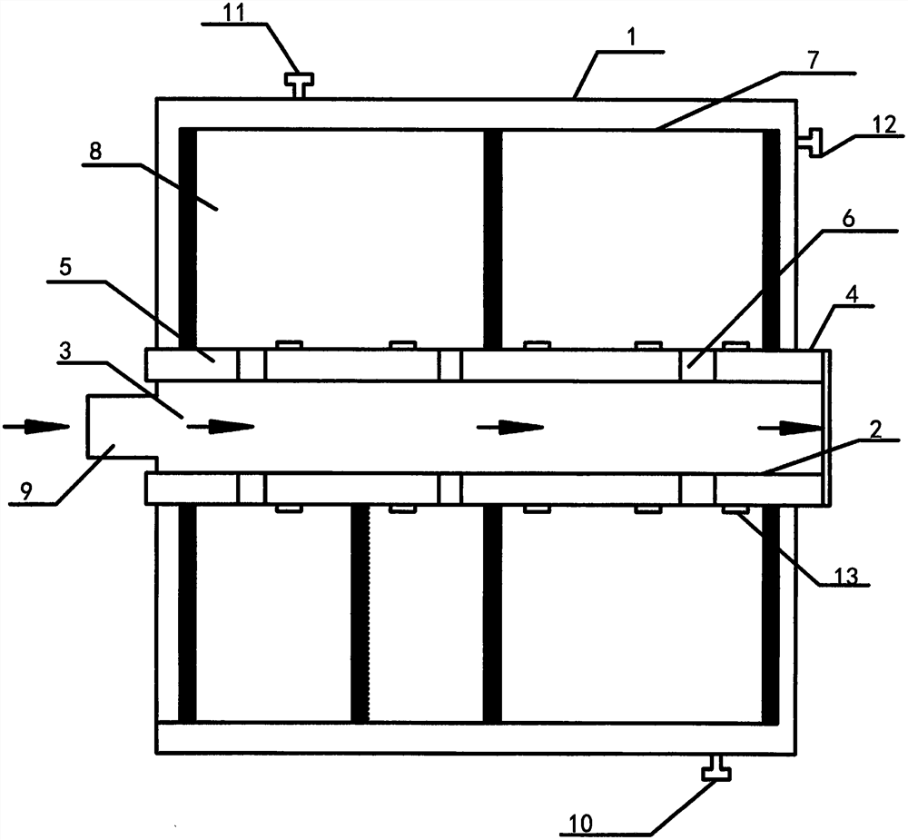
[0052] The super-gravity oxidation machine according to the present invention, such as figure 1 As shown, it has a housing 1, and a gas inlet 11 and a fluid outlet 12 are provided on the outer casing 1, the outer casing 1 for fixing the inner rotation structure, and is supported with the rotating structure. For the rotation structure, that is, the outer casing 1 is provided on the center axis of the outer casing 1 to provide a power-driven hollow rotation shaft 2, and for the selection of the power, in the present embodiment, the hollow shaft 2 and the motor connection are selected to be realized after the motor is activated. The drive rotation of the shaft 2 is rotated. Further, a fluid inlet 9 is provided on the rotating shaft 2, and the sealing structure is provided with the fluid inlet 9, the rotating shaft 2 is a hollow structure to achieve the formation of the fluid passage 3 in the hollow portion in the shaft 2. In the present embod...
Embodiment 2
[0058] Example 2 Sulfur Recycling Exhaust Gas Treatment Device
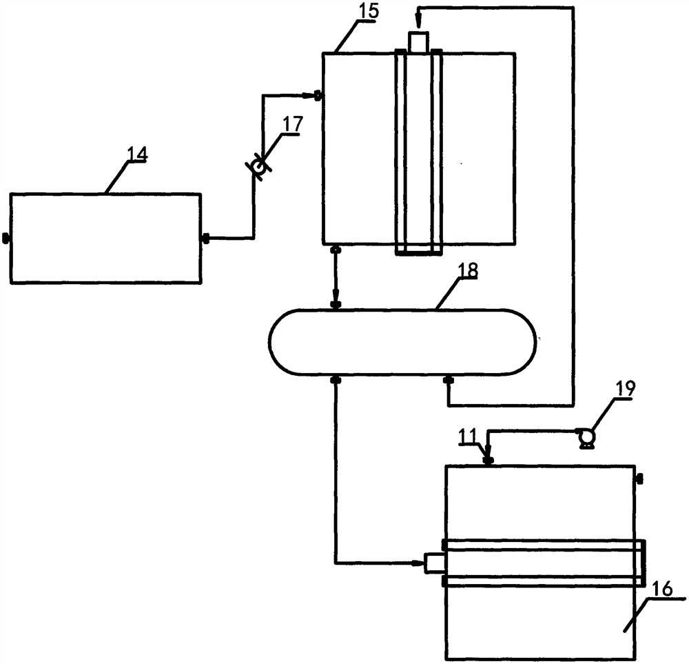
[0059] Sulfur recovery exhaust gas treatment device, such as figure 2 As shown, it is provided with an incinerator 14, and the incinerator 14 has an exhaust gas inlet;
[0060] The gas outlet connection of the incinerator 14 is provided with an overweight force 15;
[0061] The fluid outlet of the super-gravity machine 15 is provided with a fluid inlet of the base liquid circulation tank 18;
[0062] The base liquid exit of the base liquid circulation tank 18 and the fluid inlet of the super-gravity machine 15 are connected, the salt solution of the base liquid circulation tank 18 and the fluid inlet of the overweight oxidation machine 16 are connected.
[0063] As a preferred embodiment, the oxide fan 19 can be provided with the gas inlet 11 of the super gravity oxidation machine 16.
[0064] Preferably, the heat exchanger 17 is provided with the exhaust air outlet of the incinerator.
[0065] As an embodiment that ...
Embodiment 3
[0069] Sulfur recovery exhaust treatment process, including the steps of:
[0070] (1) The sulfur tail gas enters the incinerator, at 500 ° C, combustion treatment;
[0071] (2) Cooling treatment after the burning gas is taken until the gas temperature is 250 ° C;
[0072] (3) The treated gas enters the filler region via the super - gravity gas gas inlet, the concentration of 20-30 wt% sodium hydroxide solution is fluid passage, rotating the passage into the filler region, in the filler zone, gas fluid exchange;
[0073] (4) The liquid exchanged liquid is entered into the fluid inlet of the super - gravity oxidation machine. After the fluid passage, the rotary passage is spin into the filler region, the air enters the filler region, and the liquid oxidation is performed.
PUM
 Abstract
Description
Claims
Application Information
 - R&D
- Intellectual Property
- Life Sciences
- Materials
- Tech Scout
- Unparalleled Data Quality
- Higher Quality Content
- 60% Fewer Hallucinations
Browse by: Latest US Patents, China's latest patents, Technical Efficacy Thesaurus, Application Domain, Technology Topic, Popular Technical Reports.
© 2025 PatSnap. All rights reserved.Legal|Privacy policy|Modern Slavery Act Transparency Statement|Sitemap|About US| Contact US: help@patsnap.com


