
High-locality micro-groove electrolytic machining device and method

A processing device and processing method technology, applied in electrochemical processing equipment, metal processing equipment, processing working medium, etc., can solve the problems of fine electrode wear, troublesome operation, different sizes, etc., to achieve strong flexibility and improve localization Effect

Active Publication Date: 2021-06-18
GUANGDONG UNIV OF TECH
View PDF6 Cites 0 Cited by
  • Summary
  • Abstract
  • Description
  • Claims
  • Application Information

AI Technical Summary

Problems solved by technology

Micro-cutting technology has the advantages of high efficiency, flexibility, high degree of automation, and unlimited processing materials. However, since micro-cutting uses mechanical force to remove materials, it is inevitably accompanied by frictional heat generation between the tool and the workpiece and residual stress of the workpiece. ;Secondly, due to the high precision of micro-cutting, higher requirements are put forward for the control of machine tools, detection systems and the manufacture of micro-tools.
Laser processing has the characteristics of high efficiency, high localization, high precision, and strong processing control in the field of micro-processing, but its processing defects such as micro-cracks, heat-affected layers, and recast layers limit its application in some fields.
Chinese patent CN111958069A discloses a method and device for EDM machining surface micro-grooves. Micro-grooves are processed by EDM. However, EDM requires online preparation of tools, i.e. micromachining electrodes, and parts. Different sizes require different electrode diameters. At the same time, the loss of fine electrodes is extremely serious in the process of EDM. It is necessary to consider how to compensate in real time, which is very troublesome to operate.

Method used


Image

  • High-locality micro-groove electrolytic machining device and method
  • High-locality micro-groove electrolytic machining device and method
  • High-locality micro-groove electrolytic machining device and method

Examples


Embodiment Construction

[0030] The following will clearly and completely describe the technical solutions in the embodiments of the present invention. Obviously, the described embodiments are only some of the embodiments of the present invention, rather than all the embodiments. Based on the embodiments of the present invention, all other embodiments obtained by persons of ordinary skill in the art without making creative efforts belong to the protection scope of the present invention.

[0031] Embodiments of the invention include:

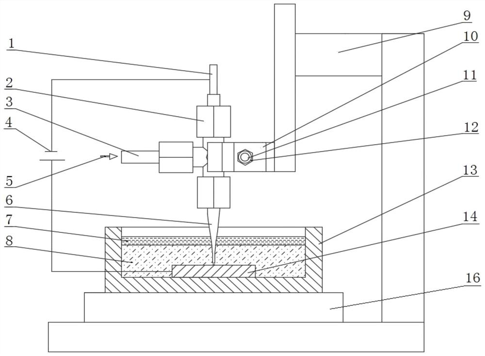
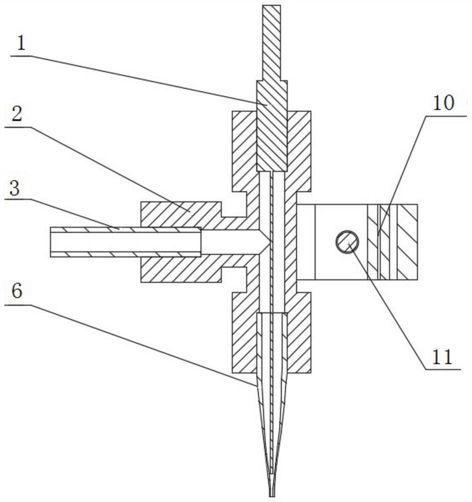
[0032] Such as Figure 1-2 As shown, a highly localized micro-groove electrolytic machining device includes a base 16, a three-degree-of-freedom motion mechanism 9, a liquid pool 13, a clamp 10, a nozzle 6, a hose 3, and a cathode material 1; the three-degree-of-freedom motion mechanism 9 is set On the base 16, the nozzle 6, the hose 3 and the cathode material 1 are connected and communicated through the three-way adapter 2, the three-way adapter 2 is connected with the...


PUM

PropertyMeasurementUnit
The inside diameter ofaaaaaaaaaa

Abstract

The invention relates to the technical field of micro-groove electrolytic machining, and particularly relates to a high-locality micro-groove electrolytic machining device. The high-locality micro-groove electrolytic machining device comprises a base, a three-degree-of-freedom movement mechanism, a liquid pool, a clamp, a spray head, a hose and a cathode material; and the three-degree-of-freedom movement mechanism is arranged on the base, the spray head, the hose and the cathode material are connected and communicate with one another through a three-way adapter, the three-way adapter is connected with the three-degree-of-freedom movement mechanism through the clamp, the liquid pool is arranged on the base and is located below the spray head, and the liquid pool is filled with high-density insoluble insulating liquid. According to the high-locality micro-groove electrolytic machining device, a mask is not needed, electrolytic machining of a high-locality micro-groove can be realized by utilizing real-time constraint of the high-density insoluble insulating liquid, so that the flexibility and the precision of electrolytic machining of the micro-groove are improved.

Description

technical field [0001] The invention relates to the technical field of micro-groove electrolytic machining, in particular to a highly localized micro-groove electrolytic machining device and method. Background technique [0002] With the progress and development of science and technology, people's research on the microcosm has been further deepened. A variety of micro-sized and micro-structured components at the millimeter, micron or even nanometer level are playing an increasingly important role in the fields of national defense, aerospace, new energy, new materials, biomedicine, and semiconductor devices. Realizing the microfabrication of microscale microstructure parts is an important development direction that the manufacturing industry is concerned about at present. [0003] The typical microstructure of microgrooves has a wide range of applications: in micro fuel cell bipolar plates, microfluidic devices such as microfluidic chips, microreactors or micro heat exchange...

Claims


Application Information

Patent Timeline
IPC IPC(8): B23H3/00B23H3/08
CPCB23H3/00B23H3/08
Inventor 陈晓磊胥中正朱嘉俊宋文锴于兆勤张永俊
Owner GUANGDONG UNIV OF TECH
Features
  • Generate Ideas
  • Intellectual Property
  • Life Sciences
  • Materials
  • Tech Scout
  • Unparalleled Data Quality
  • Higher Quality Content
  • 60% Fewer Hallucinations
Learn More