
Constant-density biomass gasifier

A gasifier and biomass technology, which is applied in the gasification process, the manufacture of combustible gas, the petroleum industry, etc., can solve the problems of overheating of the bed, the oxide layer of the furnace section, the irregular shape of the reduction layer, and the limitation of the selection of raw materials. Achieve the effect of improving the gasification time period, improving the efficiency of tar cracking, and reducing operating costs

Active Publication Date: 2021-06-18
BEIJING INSTITUTE OF TECHNOLOGYGY
View PDF2 Cites 3 Cited by
  • Summary
  • Abstract
  • Description
  • Claims
  • Application Information

AI Technical Summary

Problems solved by technology

However, in the actual operation of the existing downdraft gasifier type, the biomass material layer does not have an appropriate downward driving force, and the air distribution port of the gasification agent is directional, which may easily cause irregular shapes of the oxide layer and the reduction layer of the furnace body section. , the material layer moves down inconsistently
In addition, the fuel accumulation is bound by the accumulation angle, which makes the fuel in the furnace prone to bridging and burning through, which affects the efficiency of the thermochemical reaction in the furnace, and it is easy to cause local overheating (flying temperature) of the bed layer, so the existing gasifier type is suitable The fuel is limited to those with high bulk density, small particle size, and small stacking angle, which severely limits the selection of raw materials and increases the operating cost of biomass gasification

Method used


Image

  • Constant-density biomass gasifier
  • Constant-density biomass gasifier
  • Constant-density biomass gasifier

Examples


Embodiment Construction

[0047] In order to enable those skilled in the art to better understand the solutions of the present application, the technical solutions in the embodiments of the present application will be clearly and completely described below in conjunction with the drawings in the embodiments of the present application.

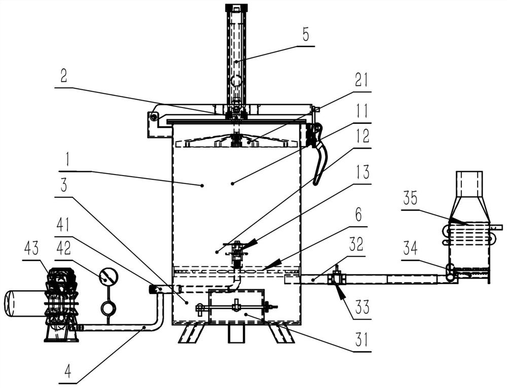
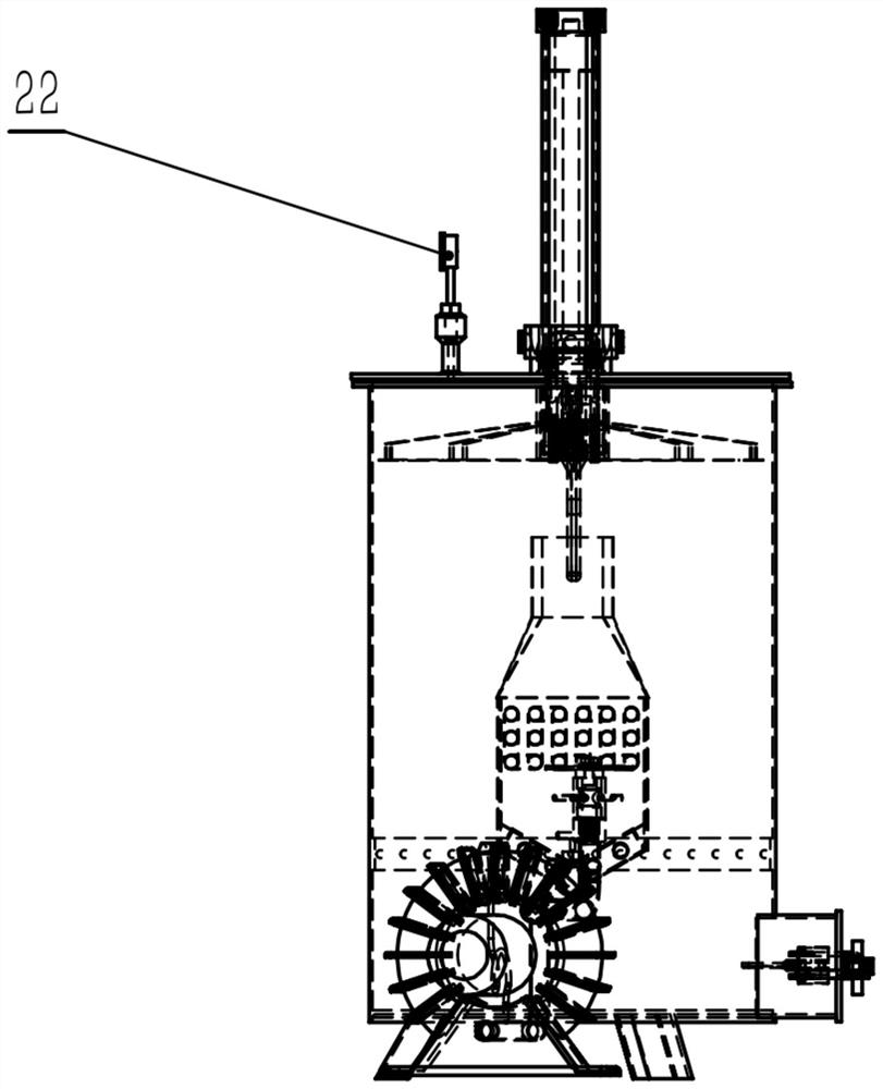
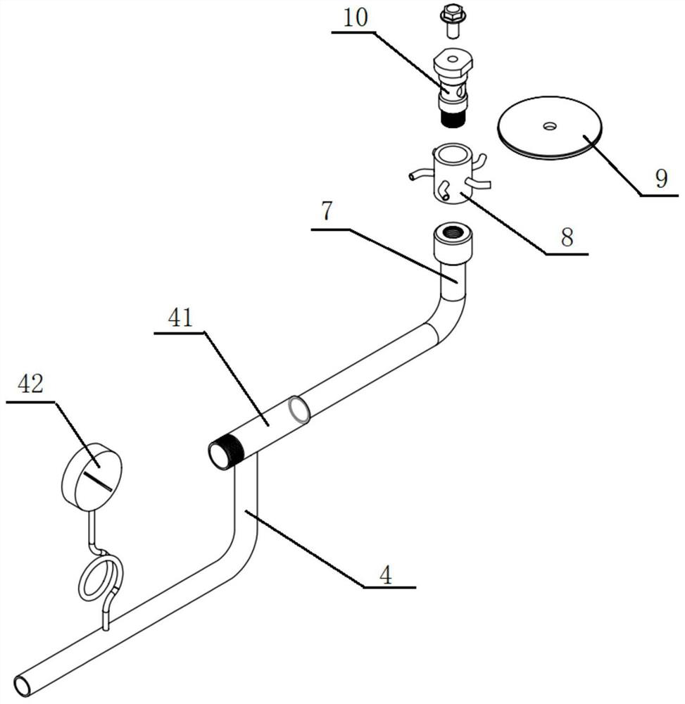
[0048] The object of the present invention is to provide a constant density biomass gasification furnace in which the fuel layer moves down at a constant density, the gasification agent is fed in from the automatic rotating nozzle in the center of the furnace body, the gas distribution is uniform, the reaction of each reaction layer is continuous and stable, and the gas production efficiency is high. . Among them, the fuel factor and combustible gas purification factor are the key factors that limit the development of biomass gasification technology. This invention is designed to solve the two factors that restrict the development of gasification technology, especially f...


PUM


Abstract

The invention provides a constant-density biomass gasifier which comprises a gasifier body, a movable gasifier cover and a self-rotating nozzle, a material pressing mechanism is arranged on the movable gasifier cover and comprises a driving device and a material pressing disc, and the material pressing disc is used for providing downward constant pressure for biomass fuel in the gasifier body under the driving of the driving device; therefore, through the material pressing mechanism arranged on the movable furnace cover, a continuous pressure from top to bottom or an intermittent impact striking effect is exerted on the biomass fuel in the material storage area in the furnace, so that a fuel layer stably descends, the compactness of the material layer is improved, and the bridging phenomenon of the material layer is eliminated; meanwhile, by means of the self-rotating nozzle, a gasifying agent evenly enters the reaction area from the center direction, an oxidation layer and a reduction layer are stable and balanced, and the burn-through phenomenon is eliminated; besides, except for filling the biomass raw materials and discharging the biochar, other operation processes are easy to realize automatic control, so that the operation cost is greatly reduced, and the economic applicability is better.

Description

technical field [0001] The invention belongs to the technical field of biomass gasification furnaces, in particular to a constant density biomass gasification furnace. Background technique [0002] As we all know, biomass is a sustainable green resource, and it is a reliable resource acquisition channel for my country's energy structure transformation, air pollution control, and CO2 emission reduction. However, due to scattered biomass resources, low bulk density, and difficulties in collection and transportation, most of the biomass has not been properly used. At present, in our country, agriculture randomly burns or discards straw, excessive and inefficient use of chemical fertilizers, all of which have caused serious environmental pollution and consumed a lot of energy of local governments. To completely solve the above problems, there is an urgent need for a large-scale high-value biomass treatment technology-biomass gasification technology. [0003] Biomass gasificati...

Claims


Application Information

Patent Timeline
Patent Type & Authority Applications(China)
IPC IPC(8): C10J3/20C10J3/66C10J3/72
CPCC10J3/20C10J3/66C10J3/725C10J3/72C10J2300/0916C10J2300/0956C10J2300/0976
Inventor 管继富张因富李雪庆
Owner BEIJING INSTITUTE OF TECHNOLOGYGY
Learn More