
Chemical vapor deposition mold

A technology of chemical vapor deposition and mold, which is applied in gaseous chemical plating, metal material coating process, coating, etc., can solve the problem of difficult control of air flow direction, and achieve the goal of improving utilization rate, promoting deposition reaction, and reasonable structural design Effect

Active Publication Date: 2021-06-18
SHAOXING RES INST OF SHANGHAI UNIV +1
View PDF7 Cites 1 Cited by
  • Summary
  • Abstract
  • Description
  • Claims
  • Application Information

AI Technical Summary

Problems solved by technology

Although this technology overcomes the above-mentioned disadvantages of adding a gas mixing chamber outside the mold, it is difficult to control the direction of the airflow finally obtained by using this method

Method used


Image

  • Chemical vapor deposition mold
  • Chemical vapor deposition mold
  • Chemical vapor deposition mold

Examples


Embodiment 1

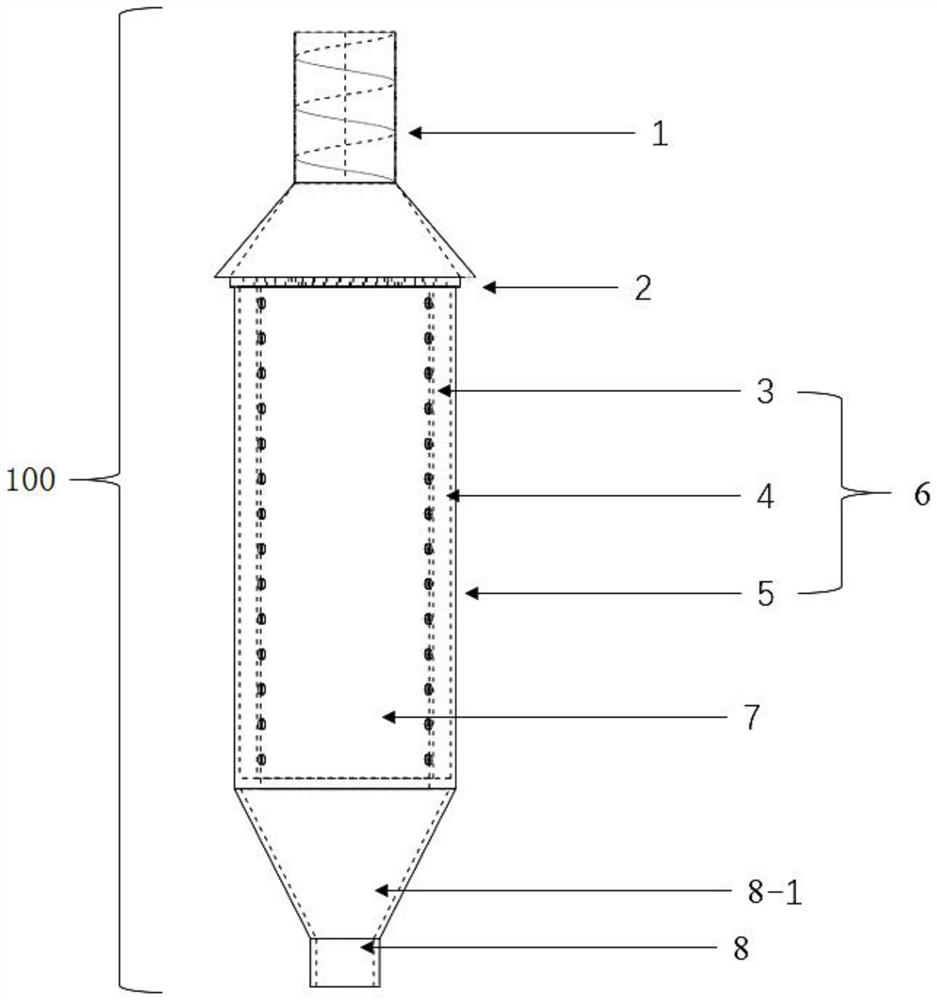
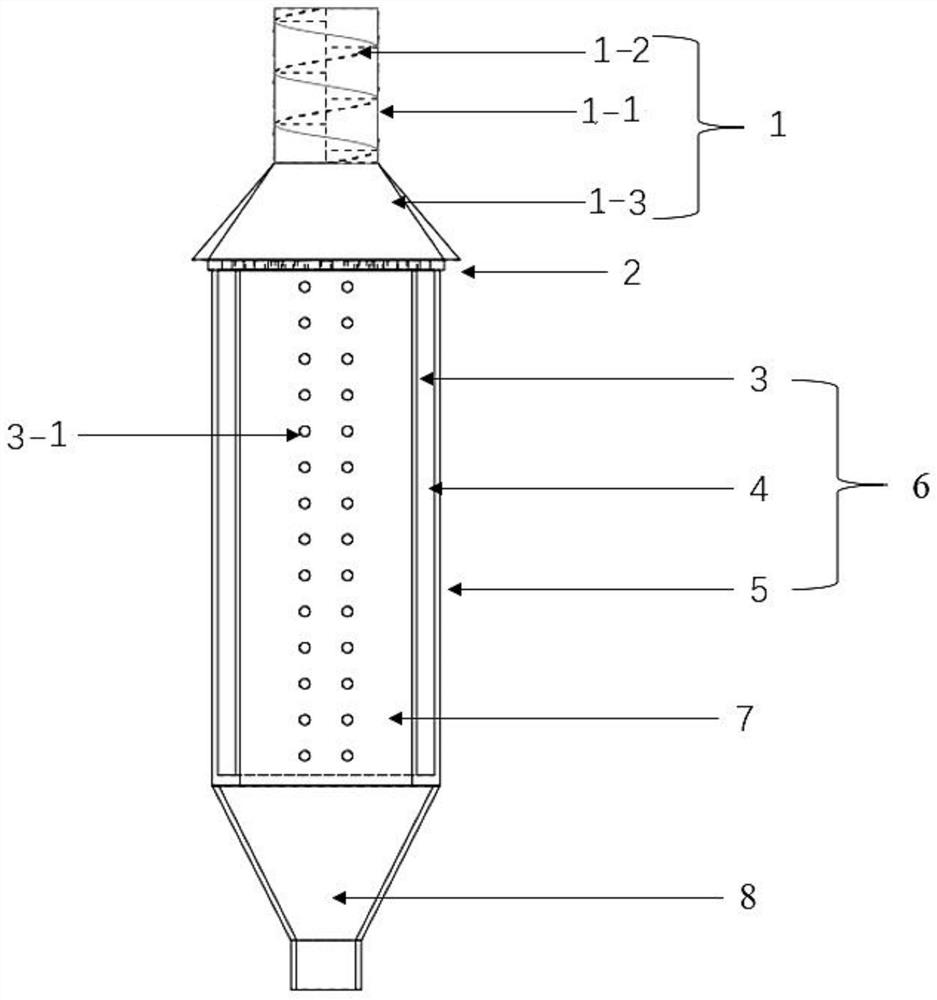
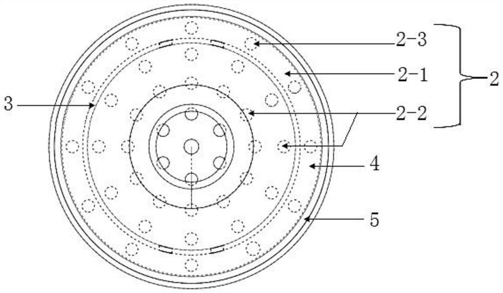
[0033] Such as Figure 1-3 As shown, the present embodiment provides a chemical vapor deposition mold 100 including a porous prefabricated reaction chamber 6, a intake pipe 1, and an air tube 8, a hole preform reaction chamber 6 includes a sealing outer wall 5 and a sealing outer wall 5 The inner belt hole inner wall 3, in the hole inner wall 3 forms a central reaction chamber 7, and the sealing outer wall 5 is formed between the cavity 4 between the hole inner wall 3, and the central reaction chamber 7 is used to place a prefabricate; the hollow cavity 4 One end is closed, the other end is open or opened, and the first vent is opened; the side wall of the hole in the bore is uniformly opened with several second vent holes 3-1; one end of the hole preform reaction chamber 6 is provided with intake pipe 1, the other end The air tube 8 is provided, and the closure of the hollow cavity 4 is provided close to the air tube 8. The spiral surface 1-2 is arranged axially in the intravation...


PUM


Abstract

The invention discloses a chemical vapor deposition mold and belongs to the field of composite material preparation. The chemical vapor deposition mold comprises a perforated preform reaction cavity; the perforated preform reaction cavity comprises a sealed outer wall and a perforated inner wall; a central reaction cavity is formed in the perforated inner wall; a hollow cavity is formed between the sealed outer wall and the perforated inner wall; one end of the hollow cavity is closed, and the other end is open or provided with a first vent hole; a second vent hole is formed in the side wall of the perforated inner wall; and a gas inlet pipe is arranged at one end of the perforated preform reaction cavity, and a gas outlet pipe is arranged at the other end of the perforated preform reaction cavity. By means of the hollow cavity, gas flow can enter the central reaction cavity in the radial direction, the other path of gas directly enters the central reaction cavity in the axial direction, two paths of gas flow in the vertical direction enable the gas flow around a carbon fiber woven part preform to enter the preform deeper, deposition reaction is promoted, and the deposition efficiency is improved; and the utilization rate of the gas can be improved on the premise of uniformly mixing multiple paths of gas, the composite material with more uniform density distribution can be quickly prepared, and the practicability is high.

Description

Technical field [0001] The invention belongs to the preparation of composite materials, and a high strength composite material is prepared according to chemical vapor deposition methods, and more particularly to a chemical vapor deposition mold. Background technique [0002] Carbon fiber reinforced carbon matrix composites, that is, a C / C composite material is a high-strength composite material obtained by machining by carbon fiber or carbon fiber braid as a reinforcing material, graphite or carbon. The commonly used method is a chemical vapor deposition method, and a porous carbon fiber fabric is used as a preform, hydrocarbon (CH) 4 , C 3 Hide 6 The et al. As a precursor in a high-temperature vacuum environment, a C / C composite is finally formed by regulating temperature, pressure, retention time, precursor concentration, and other factors. C / C-BN composites are based on C / C composites, using BCL 3 NH 3 As the precursor, the composite obtained by the chemical vapor depo...

Claims


Application Information

Patent Timeline
Patent Type & Authority Applications(China)
IPC IPC(8): C23C16/455
CPCC23C16/45561C23C16/45565C23C16/45502Y02P40/57
Inventor 李爱军刘瑶瑶贾林涛王梦千茅思佳张军军朱界张丹
Owner SHAOXING RES INST OF SHANGHAI UNIV
Learn More