
Design method of magnetorheological damper

A magneto-rheological shock absorber and magneto-rheological shock absorber technology, applied in the direction of shock absorber, shock absorber, spring/shock absorber, etc., can solve the problem of large volume of energy conversion mechanism and state feedback sensor Problems such as low utilization rate of variable fluid, limited range of controllable damping force and dynamic damping ratio, etc., achieve the effects of improving energy conversion efficiency, easy protection, and increasing the range of dynamic damping ratio

Pending Publication Date: 2021-06-18
ZHEJIANG NORMAL UNIVERSITY
View PDF7 Cites 0 Cited by
  • Summary
  • Abstract
  • Description
  • Claims
  • Application Information

AI Technical Summary

Problems solved by technology

[0003] For this reason, the present invention provides a method for designing a magnetorheological shock absorber, which is used to overcome the low utilization rate of magnetorheological fluid in the magnetorheological shock absorber in the prior art, and the limited range of controllable damping force and dynamic damping ratio , the energy conversion mechanism and the state feedback sensor are too large

Method used


Image

  • Design method of magnetorheological damper
  • Design method of magnetorheological damper
  • Design method of magnetorheological damper

Examples


Embodiment Construction

[0026] In order to make the purpose and advantages of the present invention clearer, the present invention will be further described below in conjunction with the embodiments; it should be understood that the specific embodiments described herein are only used to explain the present invention, and are not intended to limit the present invention.

[0027] Preferred embodiments of the present invention are described below with reference to the accompanying drawings. It should be understood by those skilled in the art that these embodiments are only used to explain the technical principle of the present invention, and are not intended to limit the protection scope of the present invention.

[0028] It should be noted that, in the description of the present invention, the terms "upper", "lower", "left", "right", "inner", "outer" and other terms indicated in the direction or positional relationship are based on the drawings. The direction or positional relationship shown is only fo...


PUM


Abstract

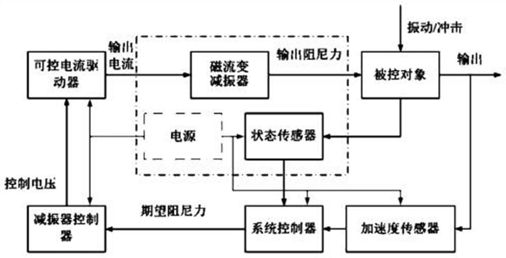
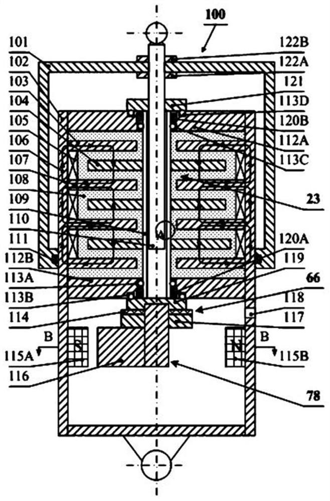
The invention relates to a design method of a magnetorheological damper. The magnetorheological damper comprises a pure shear type magnetorheological damper, an energy feedback mechanism for converting mechanical energy into electric energy and a rotating speed sensor. Linear motion of a linear magnetorheological damper piston rod is converted into rotary motion through a ball screw pair mechanism, a shearing mode in magnetorheological fluid working modes is effectively utilized, and the damping force stepless controllable performance of the magnetorheological damper is achieved by arranging a shearing disc, a shearing circular ring and a corresponding electromagnetic coil. Due to the fact that only the magnetorheological fluid shearing mode is used, the dynamic damping ratio range of the damper can be effectively widened, and the damper has a more effective control range for a high-speed impact / low-speed vibration control system. Due to the fact that the pure shear type magnetorheological damper is connected with the energy feedback mechanism in series, under the condition that the size is certain, when the piston rod bears the same pull pressure, energy conversion of the energy feedback mechanism can be maximized, and the energy conversion efficiency is effectively improved.

Description

technical field [0001] The invention relates to the technical field of shock absorbers, in particular to a design method of a magnetorheological shock absorber. Background technique [0002] Magnetorheological shock absorber is one of the typical applications of magnetorheological fluid, with excellent semi-active actuator performance, including fast response, damping force can be continuously adjusted by adjusting the excitation current, simple structure, good durability and low power consumption, and is fully replaceable in the form factor and mounting conditions of passive shock absorbers. In the past two decades, magnetorheological dampers have been studied and used to form semi-active vibration / shock control systems, including anti-vibration systems for buildings, car suspension systems, train suspension systems, car seat suspension systems, Helicopter horizontal rotor systems and other vibration / shock control systems. However, the utilization rate of magnetorheologic...

Claims


Application Information

Patent Timeline
Patent Type & Authority Applications(China)
IPC IPC(8): F16F9/53
CPCF16F9/535
Inventor 王智深贺新升张可周崇秋陈俊元
Owner ZHEJIANG NORMAL UNIVERSITY
Learn More