Double-layer sheath permanent magnet motor rotor structure

A permanent magnet motor and rotor structure technology, applied in the direction of motor, magnetic circuit shape/style/structure, magnetic circuit rotating parts, etc., can solve the problems of low strength and low utilization rate of permanent magnet materials, and achieve good stability, Avoid high temperature demagnetization and strengthen the structure

Active Publication Date: 2021-06-18
XI AN JIAOTONG UNIV +1
View PDF4 Cites 0 Cited by
  • Summary
  • Abstract
  • Description
  • Claims
  • Application Information

AI Technical Summary

Problems solved by technology

[0005] The invention proposes a double-sheathed permanent magnet motor rotor structure to solve the problems of low strength and low utilization rate of permanent magnet materials in the existing rotor structure

Method used


Image

  • Double-layer sheath permanent magnet motor rotor structure
  • Double-layer sheath permanent magnet motor rotor structure
  • Double-layer sheath permanent magnet motor rotor structure

Examples


Embodiment 1

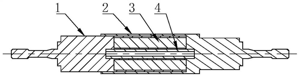
[0029] Embodiment 1: as figure 1 The rotor structure of a double-sheathed permanent magnet motor shown includes a first mandrel 1 , a second mandrel 2 , a permanent magnet unit 3 and a third mandrel 4 . The material of the first mandrel 1 and the second mandrel 2 is non-magnetic alloy steel and the outer surface is plated with tin bronze. The non-magnetic material can weaken the transmission path of magnetic flux leakage, reduce magnetic flux leakage, and improve motor performance; tin Bronze is used to reduce wind friction loss, thereby reducing heat generation and limiting rotor temperature rise. The material of the third mandrel 4 is a magnetic permeable alloy material, and the material of the permanent magnet unit 3 is a samarium cobalt permanent magnet material with a small temperature coefficient and a high working temperature.

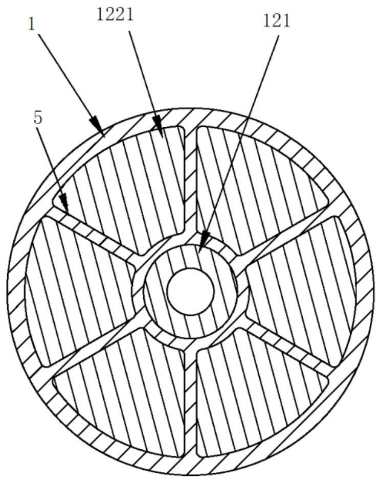
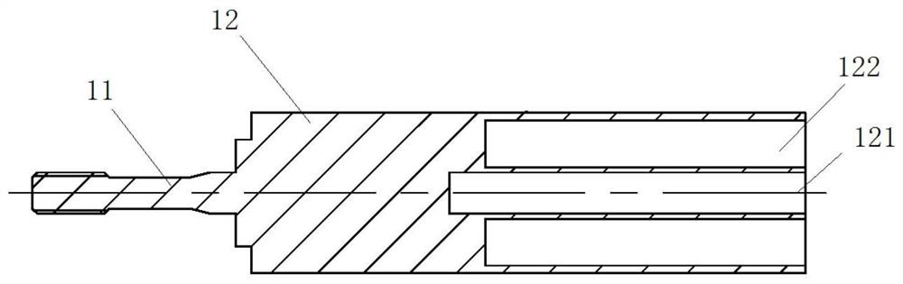
[0030] Such as figure 2 , 3 As shown, the first mandrel 1 is a stepped shaft structure, including a first end 11 and an inner sheath 12 int...


PUM


Abstract

The invention relates to the technical field of motors, and in particular relates to a double-layer sheath permanent magnet motor rotor structure which comprises a first core shaft, a second core shaft, a third core shaft and a plurality of permanent magnet units, a first groove body and a second groove body are formed in one end of the first core shaft, the second groove body is located on the outer side of the first groove body, a plurality of reinforcing ribs are uniformly distributed in the second groove body along the axial direction, the second groove body is equally divided into a plurality of sub-groove bodies by the plurality of reinforcing ribs, and the permanent magnet units are embedded into the sub-groove bodies; the outer wall of the first core shaft is sleeved with at least one part of the second core shaft, and a third groove body is formed in the end, close to the first core shaft, of the second core shaft; the two ends of the third core shaft abut against the groove bottoms of the first groove body and the third groove body respectively. According to the double-layer sheath permanent magnet motor rotor structure provided by the invention, the problems of low strength and relatively low utilization rate of a permanent magnet material of an existing rotor structure are solved.

Description

technical field [0001] The invention relates to the technical field of motors, in particular to a double-sheathed permanent magnet motor rotor structure. Background technique [0002] In recent years, the continuous development of power electronics technology and the continuous improvement of high-frequency power supply technology for motors have greatly improved the feasibility of the successful application of ultra-high-speed motors. The speed of ultra-high-speed motors can reach tens of thousands or even hundreds of thousands of revolutions per minute. Due to the use of permanent magnet rotor structure, the internal structure of the motor is very compact, and its size is much smaller than that of medium and low-speed motors of the same power. This makes ultra-high-speed The motor has extremely high power density, and at the same time it also has the advantages of high efficiency and good dynamic performance. Therefore, ultra-high-speed motors have broad application prosp...

Claims


Application Information

Patent Timeline
Patent Type & Authority Applications(China)
IPC IPC(8): H02K1/27H02K1/28H02K7/00
CPCH02K1/2706H02K1/28H02K7/003Y02T10/64
Inventor 彭学院黄海洋李佐良冯健美张兆君
Owner XI AN JIAOTONG UNIV
Why Eureka
Try Eureka