Numerical control machine tool thermal error self-adaptive compensation method

An adaptive compensation and CNC machine tool technology, which is applied in the direction of program control, computer control, general control system, etc., can solve the thermal error adaptive compensation method that does not mention thermal error, ignores the heat conduction process, and does not consider the influence of the heating of the screw bearing seat and other problems, to achieve the effect of reducing processing time, reducing scrap rate, and reducing processing energy consumption

Inactive Publication Date: 2021-06-22
DALIAN UNIV OF TECH
View PDF10 Cites 3 Cited by
  • Summary
  • Abstract
  • Description
  • Claims
  • Application Information

AI Technical Summary

Problems solved by technology

In 2015, Feng et al. published the article "Thermally induced positioning error modeling and compensation based on thermal characteristic analysis" in Volume 93 of "International Journal of Machine Tools&Manufacture". They analyzed the heat transfer mechanism of the nut, ignored its heat conduction process, and derived the heating temperature The temperature prediction model of the nut during the cooling process, but does not consider the influence of the heating of the screw bearing housing
[0005] Through the analysis of the above research, it is found that the above papers and patents lack the research on the thermal coupling behavior of the lead screw and the thermal elongation response process of the feed shaft with a specific structure, and there is no mention of thermal error adaptive compensation that can correct the thermal parameters of the model in real time method

Method used


Image

  • Numerical control machine tool thermal error self-adaptive compensation method
  • Numerical control machine tool thermal error self-adaptive compensation method
  • Numerical control machine tool thermal error self-adaptive compensation method

Examples


Embodiment Construction

[0069] In order to make the technical solution and beneficial effects of the present invention clearer, the present invention will be described in detail below in conjunction with specific implementations of thermal error adaptive compensation of CNC machine tools and with reference to the accompanying drawings. This embodiment is carried out on the premise of the technical solution of the present invention, and provides detailed implementation and specific operation process, but the protection scope of the present invention is not limited to the following embodiments.

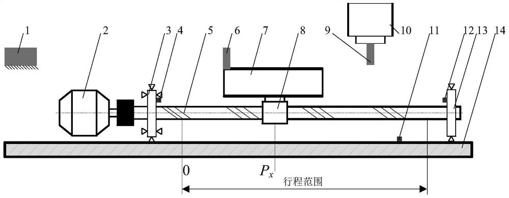
[0070] Taking the thermal error adaptive compensation of the Y axis of a vertical machining center as an example, the implementation of the present invention will be described in detail. The maximum moving speed of the Y-axis is 24000mm / min, and the travel range is 0-550mm.

[0071] The first step is to identify the thermal characteristic parameters of the feed shaft

[0072] The first temperature sensor 4, t...


PUM


Abstract

The invention belongs to the field of numerical control machine tool error compensation, and discloses a numerical control machine tool thermal error self-adaptive compensation method, which comprises the following steps of: obtaining a thermal error of a feed shaft and a corresponding key point temperature by adopting a laser interferometer and a temperature sensor according to a specific measurement mode; establishing a thermal error prediction model of the lead screw under the excitation of the multi-time-varying dynamic heat source; automatically identifying thermal characteristic parameters in the temperature field prediction model by adopting an interior point method; establishing an adaptive adjustment model for a friction heat generation coefficient Q in the thermal error prediction model under the excitation of the multi-time-varying dynamic heat source; providing a thermal error self-adaptive compensation method capable of correcting the friction heat generation coefficient Q in real time by considering the short-term friction characteristic change of the lead screw nut pair; and finally, compensating the thermal error of the machine tool through a thermal error compensation system. The numerical control machine tool thermal error self-adaptive compensation method is high in prediction precision, the problem that thermal error compensation precision fluctuates due to short-term friction characteristic changes is solved, and the robustness of the thermal error compensation method is improved.

Description

technical field [0001] The invention belongs to the field of error compensation of numerical control machine tools, in particular to an adaptive compensation method for thermal errors of numerical control machine tools. Background technique [0002] The thermal error of the machine tool is one of the important factors leading to the decrease of the stability and precision of the high-end CNC machine tool. Literature and previous test results show that the error caused by thermal deformation in the process of precision machining can reach 40-70% of the total error of the machine tool. The existence of machine tool thermal errors leads to low machining accuracy and high scrap rate of parts; in order to reduce thermal errors, a heat engine is required after the machine tool is turned on, which consumes a lot of energy and takes a long time; precision machining also requires a constant temperature workshop, which leads to higher parts processing costs. [0003] There are two me...

Claims


Application Information

Patent Timeline
Patent Type & Authority Applications(China)
IPC IPC(8): G05B19/404
CPCG05B19/404G05B2219/35408
Inventor 刘阔崔益铭宋磊刘海宁韩伟王永青
Owner DALIAN UNIV OF TECH
Why Eureka
Try Eureka