Welding of can bodies

A technology of tank body and welding roller, applied in welding equipment, welding equipment, auxiliary welding equipment, etc., can solve problems such as lack of skills, lack of clear understanding of welding process, and decreased productivity

Pending Publication Date: 2021-06-22
CROWN PACKAGING TECH
View PDF9 Cites 0 Cited by
  • Summary
  • Abstract
  • Description
  • Claims
  • Application Information

AI Technical Summary

Problems solved by technology

Adjustments can be made to correct overlap and extrusion levels, but users often make incorrect adjustments due to lack of proper skill and a clear understanding of the welding process
Therefore, the tuning method becomes a trial and error process
In addition, manual adjustments often result in machine downtime and consequently reduced productivity

Method used


Image

  • Welding of can bodies
  • Welding of can bodies
  • Welding of can bodies

Examples


Embodiment Construction

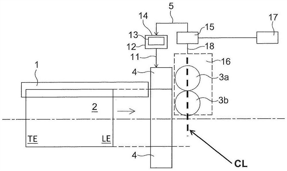
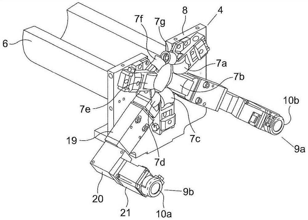
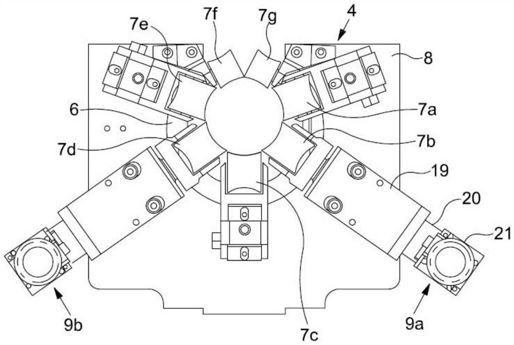
[0048] Embodiments of the present invention aim to provide closed-loop adjustment of the calibration unit of the welding station in order to automatically maintain a satisfactory weld thickness and / or weld quality for cylindrical tanks. figure 1 A welding station implementing such a closed-loop control is schematically shown. The station comprises a Z-shaped bar 1 along which a rolled metal cylinder 2 is conveyed towards a pair of opposing welding rolls 3a, 3b. As noted above, the function of the Z-bar is to bring the opposing edges of the cylinder into a substantially correct overlapping configuration as the cylinder moves away from the end of the Z-bar. A calibration unit 4 is located between the end of the Z-bar and the welding roller. The function of the calibration unit 4 is to control the cylinder overlap by making small adjustments to the circumference of the cylinder 2 . Various components of the welding station have been omitted from the drawings for the sake of bre...


PUM


Abstract

Apparatus for controlling a welding station used for welding seams extending along cylindrical can bodies, the welding station comprising a pair of welding rolls and a calibration unit for causing a desired cylinder overlap during welding. The calibration unit is adjustable along at least three different adjustment axes. The apparatus comprises: a weld monitor configured to monitor welded seams and provide an electrical signal indicative of weld thickness at a series of predetermined points along the seam length; a controller configured to receive said electrical signal and to be responsive to the signal to generate one or more control electrical signals; and a plurality of adjustment mechanisms for coupling to the calibration unit, or forming part of the calibration unit. The adjustment mechanisms are configured to receive the control electrical signal(s) and to be responsive thereto to adjust the calibration unit relative to one or more of said three adjustment axes, to provide the desired cylinder overlap and/or a desired weld quality.

Description

technical field [0001] The present invention relates to tank welding, and more particularly to methods and apparatus for monitoring and controlling weld quality by providing closed loop feedback and regulation of the welding process. Background technique [0002] A typical three-piece tank includes a cylindrical tank body and top and bottom ends sewn to the tank body. The can body is formed by crimping a flat rectangular blank into a cylinder so that the edges of the blank overlap. The cylinder is then moved past opposing welding rollers to weld the longitudinal seam of the can body. Welding rollers act as electrodes, conducting high currents through the metal of the cylinder to weld the overlapping ends of the cylinder together in a series of spaced but overlapping weld nuggets. Typically, a flat copper wire is located around each welding roll and acts as a sacrificial electrode to protect the surface of the welding roll. In a typical setup, a continuous copper wire is f...

Claims


Application Information

Patent Timeline
Patent Type & Authority Applications(China)
IPC IPC(8): B23K37/053B23K31/12B23K101/12
CPCB23K2101/125B23K37/0538B23K31/125B23K11/066B23K37/0443B23K37/0535
Inventor 若昂·费尔南多·法尼科·马丁斯马克·大卫·索利斯史蒂芬·罗伯特·阿内尔
Owner CROWN PACKAGING TECH
Why Eureka
Try Eureka