Low-temperature adsorption and high-temperature desorption efficient oil gas recovery method

A recovery method, oil and gas technology, applied in separation methods, chemical instruments and methods, gas treatment, etc., can solve problems such as unfavorable treatment and utilization, uneven regeneration, and reduction of regeneration tail gas concentration, so as to achieve efficient utilization and ensure stable operation. , the effect of high oil and gas concentration

Pending Publication Date: 2021-06-29
周静怡
View PDF7 Cites 1 Cited by
  • Summary
  • Abstract
  • Description
  • Claims
  • Application Information

AI Technical Summary

Problems solved by technology

The disadvantages are: ① When dealing with high-concentration oil and gas, due to the large amount of heat released by the oil and gas during the adsorption process, the temperature rise of the adsorbent bed is relatively large, and a "hot spot" is formed locally in the bed. If the control is not timely, it may cause the activated carbon to spontaneously ignite
When heating and regenerating, if the heating medium is not passed in, because activated carbon is a thermally poor conductor, it is easy to cause uneven temperature of the activated carbon bed layer, or even hot spots, resulting in uneven regeneration, which will reduce the performance of the adsorbent; when using heat medium, it may cause The concentration of regeneration tail gas is reduced, which is not conducive to further treatment and utilization

Method used


Image

  • Low-temperature adsorption and high-temperature desorption efficient oil gas recovery method
  • Low-temperature adsorption and high-temperature desorption efficient oil gas recovery method

Examples


Embodiment Construction

[0024] The following embodiments will further illustrate the present invention in conjunction with the accompanying drawings. For those not described, conventional technical means in the field can be used.

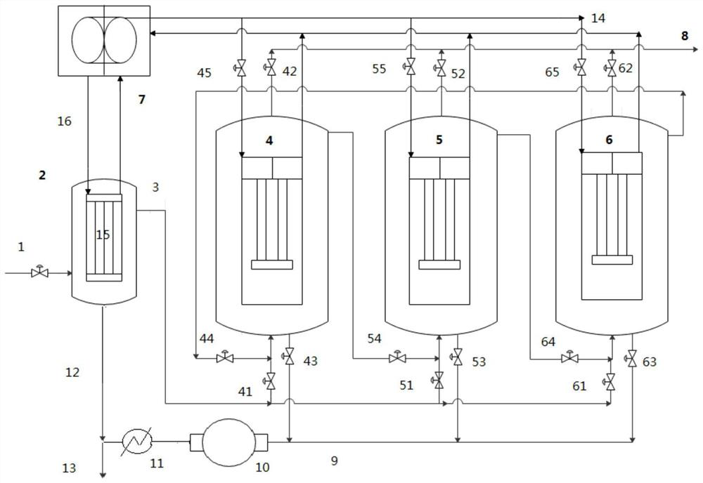
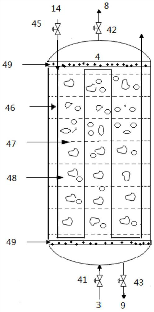
[0025]The present invention can perform adsorption at low temperature and desorption at high temperature, and adopt multiple adsorption towers (at least 3 adsorption towers, two of which are used for series adsorption, and the rest of the adsorption towers are in desorption state or pre-adsorption state) for efficient adsorption and separation The oil and gas recovery method of oil and gas components, the characteristics of this method: first, low-temperature adsorption and high-temperature desorption to achieve high-efficiency adsorption; second, adopt at least two towers in series adsorption scheme to improve the utilization efficiency of the adsorption bed; third, use heat pump method Realize the heat transfer inside the oil and gas recovery system, and reduce the energ...


PUM


Abstract

The invention discloses a low-temperature adsorption and high-temperature desorption efficient oil gas recovery method, and relates to an oil gas recovery method. Raw material oil gas is introduced into a primary cooling tower, a refrigerant in a heat pump system is used for evaporating and refrigerating in an evaporator in the tower to cool the raw material oil gas, part of heavy components and water vapor in the oil gas are condensed and separated, condensate generated by cooling enters an absorption system, and cooled low-temperature oil gas enters an adsorption unit. The adsorption unit is provided with at least three towers, two towers are connected in series for adsorption, the other tower is used for desorption and regeneration, and the three towers are alternately switched through valve control in the adsorption and desorption processes to circularly treat oil gas. The gas reaching the emission standard after adsorption is discharged. Saturated oil gas is adsorbed by the adsorption tower, heat obtained in the primary cooling tower enters a heat exchange facility in the adsorption tower by the heat pump system through refrigerant circulation of the heat pump system to heat an adsorption bed layer, vacuum desorption is carried out, and desorbed oil gas is introduced into the absorption system. Low-temperature adsorption and high-temperature desorption are realized, the oil gas recovery rate is high, the adsorbent regeneration efficiency is high, and the operation cost is low.

Description

technical field [0001] The invention relates to an oil gas recovery method, in particular to a high-efficiency oil gas recovery method for low-temperature adsorption and high-temperature desorption. Background technique [0002] In the process of filling light oil liquids, such as gasoline, naphtha, crude oil, solvent oil, etc. The gas is gradually displaced, producing a mixture of air and volatile organic compounds (oil and gas). Due to the low initial boiling point and high saturated vapor pressure of these light oil products, the concentration of oil and gas produced during the filling process is relatively high, mostly around 10-40v%. In the high temperature season in summer, the ambient temperature is high, the oil loading temperature is high, and the oil gas concentration will be higher, sometimes even reaching about 40-60v%. The volatiles generated during the oil filling process (the filling loss of light oil products is roughly equivalent to 1‰ of the oil product b...

Claims


Application Information

Patent Timeline
IPC IPC(8): B01D53/00B01D53/04
CPCB01D53/002B01D53/0423B01D53/0438B01D53/0454B01D2253/102B01D2257/70B01D2258/02B01D2259/40088
Inventor 周静怡
Owner 周静怡
Why Eureka
Try Eureka