
Outboard engine and separated lubricating system thereof

A technology of outboard motors and lubrication systems, applied in the direction of engine lubrication, closed-circuit lubrication systems, engine components, etc., can solve the problems of large consumption of lubricating oil, inability to change in time, too thick lubricating oil, etc., and achieve favorable cooling And lubrication, high viscosity, sufficient lubrication effect

Active Publication Date: 2021-06-29
SUZHOU BAISHENG POWER MACHINE
View PDF6 Cites 1 Cited by
  • Summary
  • Abstract
  • Description
  • Claims
  • Application Information

AI Technical Summary

Problems solved by technology

Although this kind of lubrication method is reliable, because the mixing ratio is a fixed value, it cannot be changed in time according to the engine working conditions, resulting in too thick lubricating oil at idle speed and excessive consumption of lubricating oil; moreover, lubricating oil participates in combustion, which is prone to carbon deposits. And a large amount of harmful substances produced by incomplete combustion are discharged with the exhaust gas of the engine to pollute the air and water

Method used


Image

  • Outboard engine and separated lubricating system thereof
  • Outboard engine and separated lubricating system thereof
  • Outboard engine and separated lubricating system thereof

Examples


Embodiment Construction

[0029] The present invention will be further described with reference to the accompanying drawings.

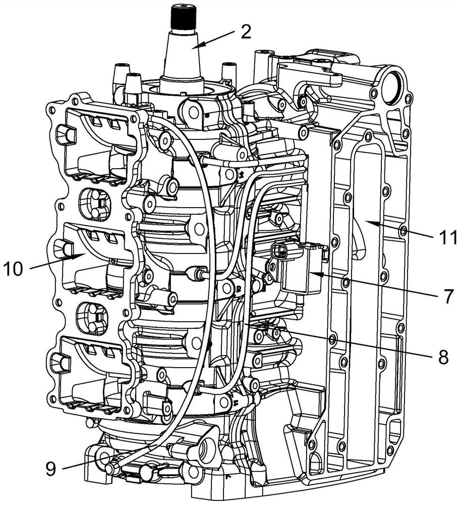
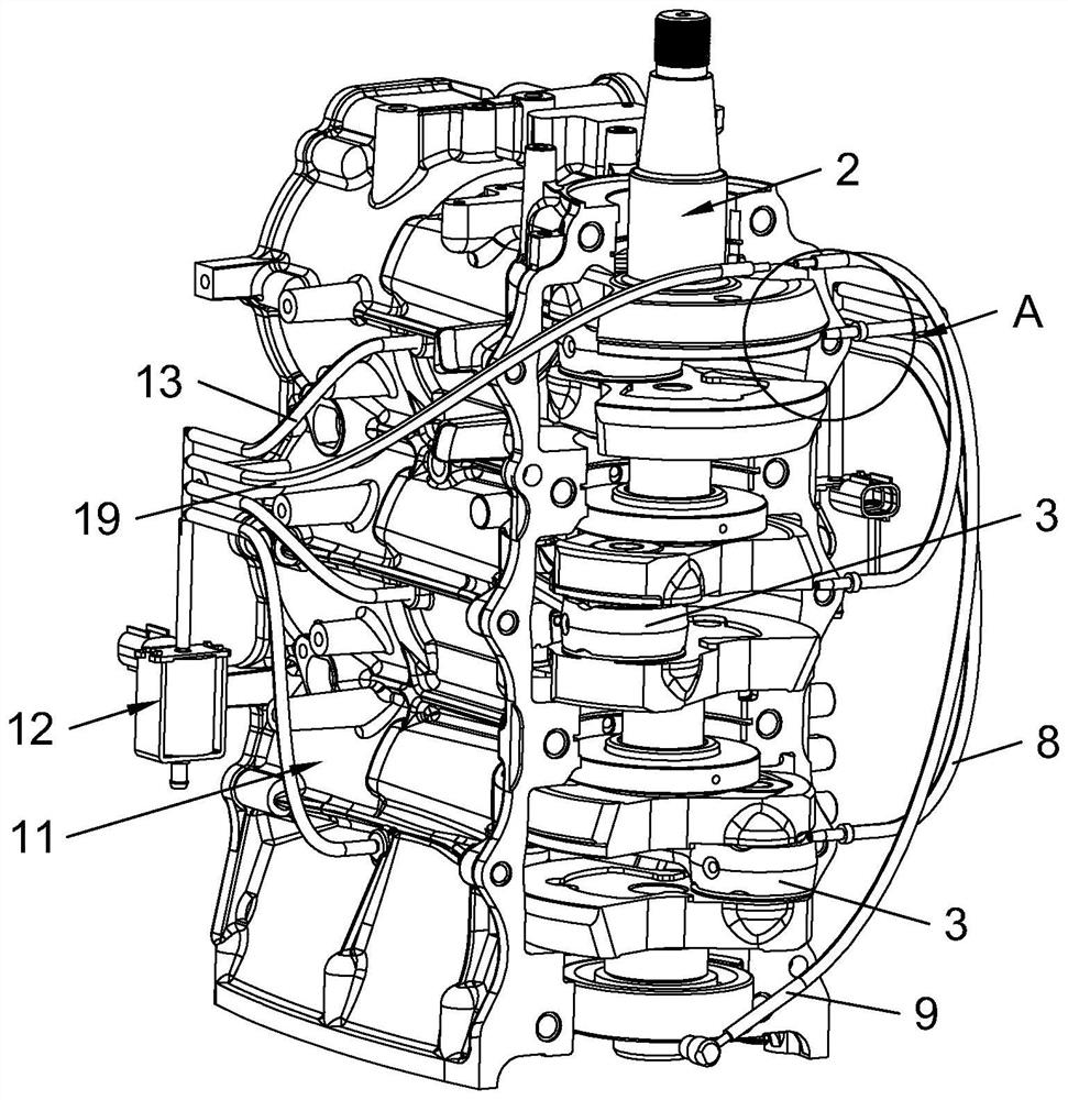
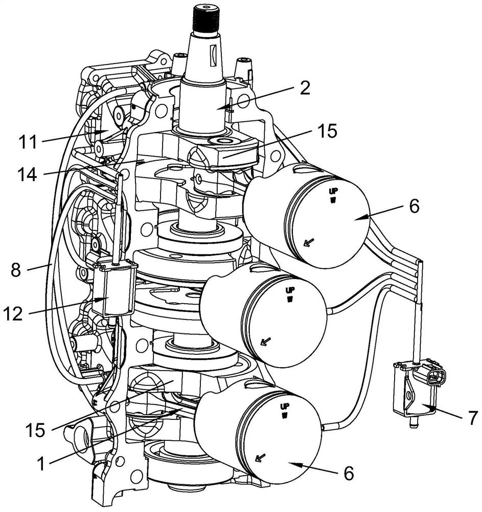
[0030] This embodiment discloses a separate lubricating system for an outboard motor, such as Figure 1-7 As shown, it includes a crankcase and a power assembly arranged in the cavity of the crankcase. The power assembly includes a connecting rod 1, a crankshaft 2, and a plurality of bearings, wherein the connecting rod 1 includes a connecting rod big end 3 and a connecting rod small end. end and the connecting rod shaft, the large end 3 of the connecting rod is hinged to the crankshaft 2 through the crank pin, the small end 4 of the connecting rod is hinged to the piston 6 through the piston pin, and the piston 6 reciprocates in the cylinder and drives the connecting rod 1 to reciprocate. The connecting rod 1 reciprocates and drives the crankshaft 2 to rotate in the crankcase; the separated lubrication system also includes a lubricating oil tank, a first oil pump 7 and a plur...


PUM


Abstract

The invention discloses a separated lubricating system of an outboard engine. The system comprises a crankcase and a power assembly arranged in a cavity of the crankcase, the system further comprises a lubricating oil tank, a first oil pump and a plurality of first oil pipes mounted on the first oil pump, the first oil pump communicates with the cavity of the crankcase through the multiple first oil pipes, and the first oil pump extracts lubricating oil from the lubricating oil tank and conveys the lubricating oil into the crankcase to lubricate the power assembly; the first oil pump is linked with the engine, so that the first oil pump conveys the lubricating oil with the oil quantity adaptive to the working condition of the engine into the crankcase; and meanwhile, the bottom of the cavity of the crankcase communicates with the upper portion of the cavity of the crankcase through a second oil pipe, so that the lubricating oil at the bottom of the cavity is conveyed to the upper portion of the cavity through the second oil pipe under the action of negative pressure. The separated lubricating system is adopted, so that the consumption of the lubricating oil can be reduced, and carbon deposition and exhaust emission can be improved; and the lubricating oil directly enters into the crankcase without being diluted by fuel oil, and the viscosity of the lubricating oil is large, so that cooling and lubrication of the power assembly are facilitated.

Description

technical field [0001] The invention relates to the technical field of motors, more specifically, it relates to outboard motors and their separate lubricating systems. Background technique [0002] At present, the lubrication method of two-stroke outboard engines generally adopts the mixed lubrication method; that is, the lubricating oil is added to the fuel according to the required ratio, and the mixture is stirred and then added to the fuel tank. When the engine is working, the mixed oil enters the crankcase after being atomized by the carburetor and then enters the cylinder to achieve the purpose of lubrication. Although this kind of lubrication method is reliable, because the mixing ratio is a fixed value, it cannot be changed in time according to the engine working conditions, resulting in too thick lubricating oil at idle speed and excessive consumption of lubricating oil; moreover, lubricating oil participates in combustion, which is prone to carbon deposits. And a ...

Claims


Application Information

Patent Timeline
Patent Type & Authority Applications(China)
IPC IPC(8): F01M1/02F01M1/04F01M9/08F01M1/12
CPCF01M1/02F01M1/04F01M9/08F01M2001/0253F01M2001/123
Inventor 夏坚朱宇翔任韦青
Owner SUZHOU BAISHENG POWER MACHINE
Learn More