Electronically-driven coupled bioelectrochemistry degradation system and method and application of electronically-driven coupled bioelectrochemistry degradation system and method

A bioelectrochemical and driven technology, applied in the field of environmental engineering, can solve the problems that the degradation system cannot degrade and process different types of substances at the same time, and the degradation is difficult

Inactive Publication Date: 2021-07-06
南京成贤环境科技有限公司
View PDF0 Cites 0 Cited by
  • Summary
  • Abstract
  • Description
  • Claims
  • Application Information

AI Technical Summary

Problems solved by technology

[0003] Moreover, the degradation system in the current prior art cannot degrade and process different types of substances at the same time, and the degradation is extremely difficult

Method used


Image

  • Electronically-driven coupled bioelectrochemistry degradation system and method and application of electronically-driven coupled bioelectrochemistry degradation system and method
  • Electronically-driven coupled bioelectrochemistry degradation system and method and application of electronically-driven coupled bioelectrochemistry degradation system and method
  • Electronically-driven coupled bioelectrochemistry degradation system and method and application of electronically-driven coupled bioelectrochemistry degradation system and method

Examples


Embodiment 1

[0030] A degradation method for an electronically driven coupled bioelectrochemical degradation system, comprising the following steps:

[0031] (1) Disperse the semiconductor mineral particles, activate the humic acid, and inoculate the soil to be treated and the anode with anaerobic sludge;

[0032] (2) Mix and stir the semiconductor mineral particles after the dispersion treatment, the humic acid after the activation treatment and the soil inoculated with anaerobic sludge to obtain a soil matrix and form a composite electron transfer network;

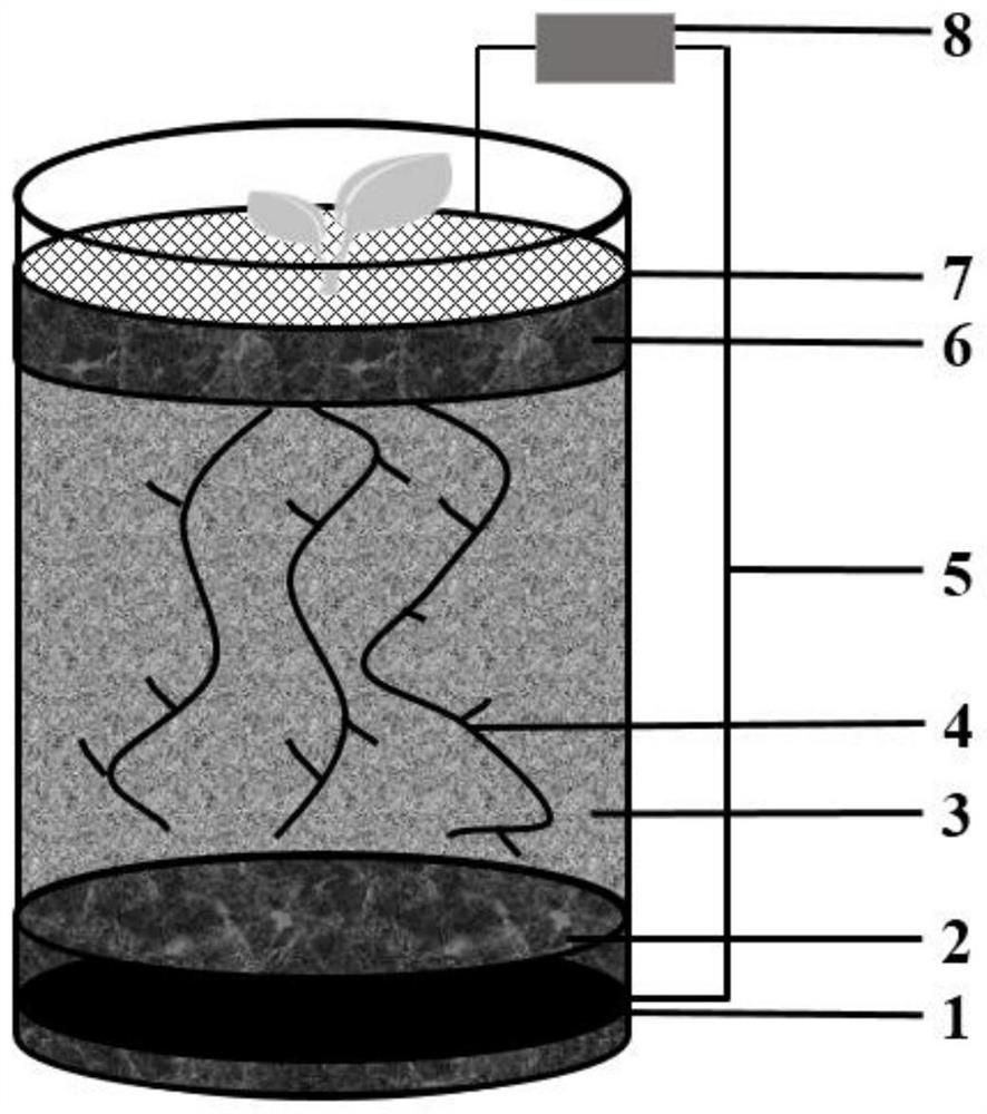
[0033] (3) Construct a degradation system. The degradation system consists of anode layer, soil matrix and cathode layer from bottom to top. Plants are planted in the soil matrix to form a plant root-anode composite area, and the degradation system is operated to achieve the degradation of pollutants.

[0034] Among them, the dispersion treatment of semiconductor mineral particles is as follows: crush and sieve the natural minerals (...

Embodiment 2

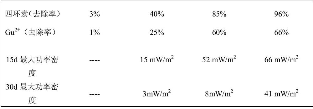
[0040] This example is basically the same as Example 1, except that the pollutant antibiotic in the soil, specifically tetracycline, has an initial concentration of 40 mg / kg.

Embodiment 3

[0042] This embodiment is basically the same as Embodiment 1, except that the pollutants in the soil are heavy metals, specifically Cu 2+ , the initial concentration is 10mg / kg.

[0043] The degradation system of the above-mentioned Examples 1-3 is degraded, and the specific process is: the degradation starts to add 10mL (10g / L) nutrient solution dissolved with sodium acetate, in addition, the nutrient solution is added every seven days to maintain the stability of the device, and the device Placed in a 30-degree incubator for cultivation.

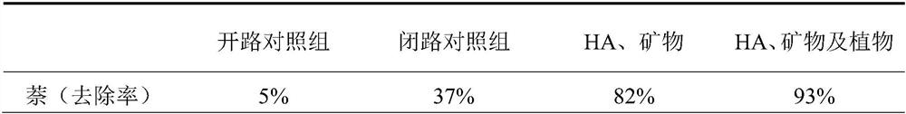
[0044] The degradation results are summarized in Table 1 below. After 45 days of treatment, the concentration of naphthalene in the soil matrix decreased by 5%, 37%, 82% and 93%, respectively. After 45 days, the addition of nutrient solution was stopped and the operation continued for 15 days. In the case of an external resistance of 10Ω, the maximum power density of the three closed-circuit test groups was 15mW / m 2 、52mW / m 2 、66mW / m 2...


PUM


Abstract

The invention discloses an electronically-driven coupled bioelectrochemical degradation system and method and application thereof. The system comprises to-be-treated soil, plants planted in the soil, a cathode layer and an anode layer which are located on the two sides of a soil matrix respectively, a wire connected between the cathode layer and the anode layer, and an external resistor connected to the wire. Semiconductor mineral particles and humus are doped in the soil matrix. The degradation system can quickly and efficiently treat high-concentration organic pollutants, antibiotics, heavy metals and combined pollution of the organic pollutants, the antibiotics and the heavy metals at the same time, and secondary pollution cannot be generated in the degradation process.

Description

technical field [0001] The invention relates to the field of environmental engineering, in particular to a system for removing refractory organic pollutants in soil and its application. Background technique [0002] The problem of soil pollution is complex and severe, especially the persistent organic pollutants (POPs) contained in soil are refractory, bioaccumulative and biotoxic, which directly threaten human health and environmental safety, and are prominent technical problems in soil pollution. . Soil microbial fuel cell (Soil-MFC) is a bioelectrochemical technology based on microbial remediation, which well inherits the advantages of microbial remediation technology. At the same time, Soil-MFC also has the ability to generate electricity in situ and use it in the purification of pollutants without external energy input; the extracellular electrons produced by electrogenic bacteria can be synchronously reduced to remove a variety of refractory organic pollutants; applie...

Claims


Application Information

Patent Timeline
Patent Type & Authority Applications(China)
IPC IPC(8): B09C1/10B09C1/08
CPCB09C1/085B09C1/105
Inventor 李先宁曹羡高昕童
Owner 南京成贤环境科技有限公司
Why Eureka
Try Eureka