Optical fiber line mirror surface polishing equipment and method

A technology of mirror polishing and optical fiber line, applied in the field of optical fiber line, can solve the problems of light energy loss, affecting the light transmittance of optical fiber line, long processing time, etc.

Active Publication Date: 2021-07-06
上海索迪龙自动化股份有限公司
View PDF3 Cites 0 Cited by
  • Summary
  • Abstract
  • Description
  • Claims
  • Application Information

AI Technical Summary

Problems solved by technology

[0002] The existing technology mainly adopts rough grinding, medium grinding, and fine grinding of optical fiber production and processing technology. The processing time is relatively long, requiring multiple people to coordinate work at the same time, and there is a certain defect rate after processing, and the smoothness after grinding cannot effectively reach the mirror surface. effect, there will be a certain loss of light energy
During the grinding process, due to extrusion and high-speed grinding, there is also a certain internal stress inside the optical fiber. The existence of internal stress also affects the light transmittance of the optical fiber and reduces the use effect of the product. The existing grinding process, in Theoretically, it has certain flaws. No matter how fine the sandpaper is, there will always be a certain roughness. It is just as close to the smooth surface as possible, so that the effect after grinding is close to the standard of use.

Method used


Image

  • Optical fiber line mirror surface polishing equipment and method
  • Optical fiber line mirror surface polishing equipment and method
  • Optical fiber line mirror surface polishing equipment and method

Examples


Embodiment Construction

[0035] The following will clearly and completely describe the technical solutions in the embodiments of the application with reference to the drawings in the embodiments of the application. Apparently, the described embodiments are only some of the embodiments of the application, not all of them. Based on the embodiments in this application, all other embodiments obtained by persons of ordinary skill in the art without making creative efforts belong to the scope of protection of this application.

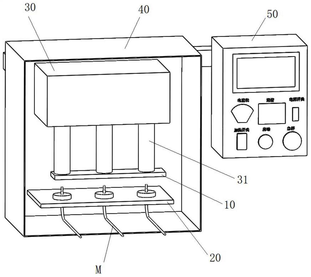
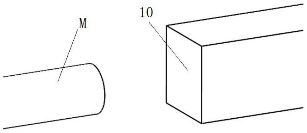
[0036] Such as figure 1 with figure 2 As shown, in one of the embodiments of the present application, a kind of optical fiber line mirror polishing equipment includes:

[0037] A mirror polishing hot stamping machine, including a hot stamping machine main body and a mirror hot stamping plate 10 movably connected with the hot stamping machine main body;

[0038] A driving mechanism 30, the driving mechanism 30 is connected to the mirror hot stamping plate 10 and drives the mirror ...


PUM


Abstract

The invention discloses optical fiber line mirror surface polishing equipment and method. The polishing equipment comprises a mirror surface polishing thermoprinting machine which comprises a thermoprinting machine main body and a mirror surface thermoprinting plate movably connected with the thermoprinting machine main body, a driving mechanism which is connected with the mirror surface thermoprinting plate and drives the mirror surface thermoprinting plate to reciprocate relative to the thermoprinting machine main body, and an optical fiber line fixing mechanism which is used for temporarily fixing multiple optical fiber lines, and the to-be-polished surfaces of the optical fiber lines face the mirror surface thermoprinting plate. The method comprises the following steps that a thermoprinting instruction for the optical fiber lines is acquired; the driving mechanism is driven to act on the mirror surface thermoprinting plate, so that the mirror surface thermoprinting plate carries out thermoprinting in the arrangement direction of the optical fiber lines; and after thermoprinting is completed, the driving mechanism restores to the initial state. The thermoprinting technology is adopted, the smooth finish of the sections of the thermoprinted optical fiber lines can effectively achieve the mirror surface effect, the mirror surface effect of the thermoprinted optical fiber lines is comparable to the smooth finish of tempered glass, light lost through the thermoprinted surfaces is not higher than 1%, and the light energy utilization rate can be effectively improved.

Description

technical field [0001] The application belongs to the technical field of optical fiber, and in particular relates to a mirror polishing device and method for optical fiber. Background technique [0002] The existing technology mainly adopts rough grinding, medium grinding, and fine grinding of optical fiber production and processing technology. The processing time is relatively long, requiring multiple people to coordinate work at the same time, and there is a certain defect rate after processing, and the smoothness after grinding cannot effectively reach the mirror surface. As a result, there will be a certain loss of light energy. During the grinding process, due to extrusion and high-speed grinding, there is also a certain internal stress inside the optical fiber. The existence of internal stress also affects the light transmittance of the optical fiber and reduces the use effect of the product. The existing grinding process, in Theoretically, it has certain flaws. No ma...

Claims


Application Information

Patent Timeline
Patent Type & Authority Applications(China)
IPC IPC(8): B41F16/00
CPCB41F16/0046B41F16/0086Y02P40/57
Inventor 邓志才周曙光陈坤速
Owner 上海索迪龙自动化股份有限公司
Why Eureka
Try Eureka