Automatic workover rig driven by power grid

A technology of workover rig and grid power, which is applied to drilling equipment, earthwork drilling, drill pipe, etc., can solve the problems of difficulty in recruiting workers in the workover industry, difficulty in installation and disassembly of equipment, and high labor intensity of workers.

Active Publication Date: 2021-07-06
中石化四机石油机械有限公司 +1
View PDF10 Cites 2 Cited by
  • Summary
  • Abstract
  • Description
  • Claims
  • Application Information

AI Technical Summary

Problems solved by technology

Conventional workover operations are not only inefficient, but also difficult to install and disassemble equipment, and the labor intensity of the workers is high. There are many problems in the wellhead operation area, such as "dangerous", "difficult", "dirty

Method used


Image

  • Automatic workover rig driven by power grid
  • Automatic workover rig driven by power grid
  • Automatic workover rig driven by power grid

Examples


Embodiment example 1

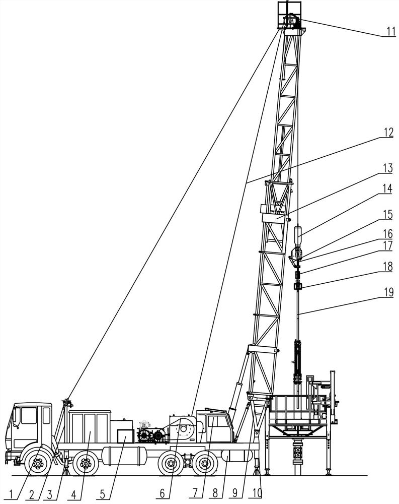
[0053] Step 1: firstly deploy the front hydraulic outrigger 3 and the rear hydraulic outrigger 10 on the self-propelled chassis 1, so that the workover rig can be stably placed on the ground;

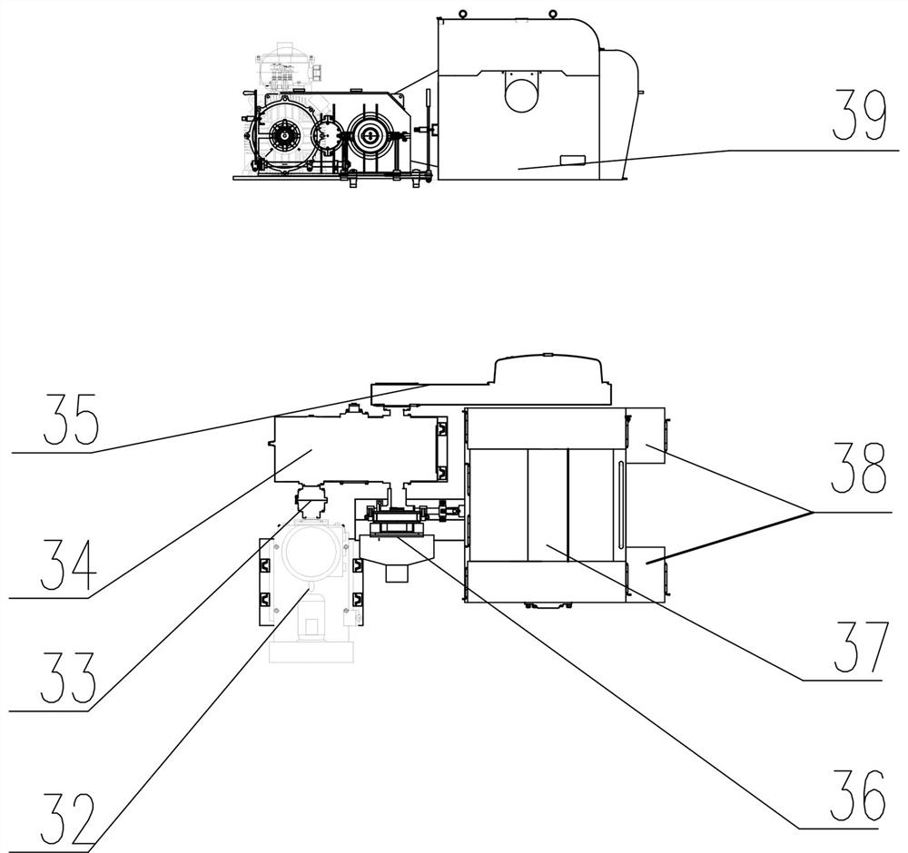
[0054] Step 2: When performing the operation of recovering the pipe string, the rear operation room 7 issues instructions, and the electric control cabinet 20 outputs electric energy to the explosion-proof frequency conversion motor 32 through the control cable 23, and the explosion-proof frequency conversion motor 32 passes through the coupling 33 and the multi-speed gear box 34 The power is transmitted to the main drum 37, and the main drum 37 unwinds the wire rope 12 and lowers the grabbing system;

[0055] Step 3: Control the lifting ring swing arm device 15 to rotate the lifting ring 16 to avoid the wellhead pipe string 19 during the lowering of the grabbing system, and control the flip box 17 to drive the hydraulic elevator 18 to turn over the grabbing string 19;

[0056] Step 4: ...

Embodiment example 2

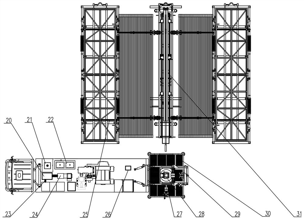
[0062] Step 1: When lowering the pipe string, adjust the height of the pipe rack 40 so that the side of the pipe string storage device 25 is higher than the side of the pipe string delivery device 31, and the pipe string storage device 25 transports the pipe string 19 to the pipe rack 40;

[0063] Step 2: The pipe string 19 rolls to the edge of the pipe string conveying device 31, and the turning hook arm 41 turns inward to send the pipe string 19 to the transfer tray 42. sent to the edge of the working platform;

[0064] Step 3: the rear operating room 7 issues instructions, and the electric control cabinet 20 controls the rotation of the multi-gear variable-speed winch 6, and the main drum 37 on the multi-gear variable-speed winch 6 is lowered to the grasping system by winding and unwinding the steel wire rope 12;

[0065] Step 4: Lower the grabbing system to the top of the column 19 on the transfer tray 42, control the flip box 17 to turn over the hydraulic elevator 18 and ...


PUM


Abstract

The invention discloses an automatic workover rig driven by power grid. A derrick front support, an electric control room and a hydraulic system are arranged at the front end of a self-propelled chassis of equipment, an electric air compressor, a multi-gear variable-speed winch and a deadline anchor are arranged in the middle of the self-propelled chassis, an operation room, an air storage tank and a derrick rear support are arranged at the tail of the self-propelled chassis, a working platform is arranged on a wellhead at the tail part of the self-propelled chassis, a tubular column storage device is connected with a tubular column conveying device and is vertically arranged on one side of the upper end surface of the working platform, one end of a steel wire rope is connected with the multi-gear variable-speed winch and the deadline anchor, the other end of the steel wire rope is connected with a grabbing system after bypassing a crown block pulley block, and the grabbing system is used for grabbing a tubular column. According to the automatic workover rig driven by the power grid, various matched devices and systems are connected with respective control systems, workers only need to conduct whole-process monitoring in a driller control room in the whole workover operation, and full-automatic operation of wellhead tubular column connection, buckling, screwing-on and screwing-off and tubular column feeding and discharging operation platforms is achieved.

Description

technical field [0001] The invention relates to the field of oil and gas field development process equipment, in particular to a grid-powered automatic workover machine. Background technique [0002] At present, domestic workover rigs are mostly powered by diesel engines, and the diesel engines drive gearboxes or torque converters to drive drawworks to realize pipe string and workover operations. This type of workover rig has a low degree of automation, and the use of diesel engines not only causes serious pollution, but also causes serious power waste. As environmental protection requirements become more stringent, it is imminent to use new energy for alternative operations. [0003] At present, the conventional minor workover operations of workover rigs in China are still mainly manual work, and most of the operators in each shift are about 6 people, including 2 wellhead fitters, 2 ground operators, 1 driller, and 1 auxiliary staff. The operating equipment includes 1 work...

Claims


Application Information

Patent Timeline
IPC IPC(8): E21B19/00E21B19/06E21B19/14E21B19/10E21B19/16E21B19/02
CPCE21B19/00E21B19/06E21B19/14E21B19/10E21B19/16E21B19/02
Inventor 李云祥刘燕彭太锋张斌许梦杰宋一刘泽华冯小东
Owner 中石化四机石油机械有限公司
Why Eureka
Try Eureka