LED light source, preparation method thereof and backlight module

A technology of LED light source and light source substrate, which is applied in the direction of light source, light source fixing, lighting and heating equipment, etc., can solve the problems of insufficient stability of green quantum film, high cost of the whole Mini LED display, serious light decay, etc.

Pending Publication Date: 2021-07-06
江西兆驰光元科技股份有限公司
View PDF0 Cites 2 Cited by
  • Summary
  • Abstract
  • Description
  • Claims
  • Application Information

AI Technical Summary

Problems solved by technology

This solution has the following problems: the light is mainly emitted from the top of the light source, showing a phenomenon that the center is bright and the surroundings are dark, that is, the luminous angle of the light source is small; wherein, the brightness of the middle part accounts for about 80% of the total brightness of the light source, and the brightness of the surroundings is about 80% of the total brightness of the light source. It accounts for about 20% of the total brightness of the light source, and the luminous angle of the light source is about 140°, which leads to uneven brightness and darkness of the quantum dot display
In order to obtain a uniform surface light source, not only the light source spacing is required to be small enough (the light source spacing in the prior art solution is usually 3mm to 5mm), but also the number of light sources in the LED light source array is sufficient, and the larger the quantum dot TV needs. The more, and the use of a thicker diffuser (the thickness of the diffuser in the prior art solution is usually 2.5mm, 2mm, etc.), which leads to the high cost of the Mini LED display
[0006] like image 3 As shown, it is the backlight module of the Mini LED quantum dot display in the prior art, which is mainly composed of the light source substrate carrying the Mini LED light source array + LED light source + diffusion sheet + red quantum film + green quantum film, and the green quantum film Insufficient stability, severe light decay during use, resulting in short life of the whole machine

Method used


Image

  • LED light source, preparation method thereof and backlight module
  • LED light source, preparation method thereof and backlight module
  • LED light source, preparation method thereof and backlight module

Examples


Embodiment 1

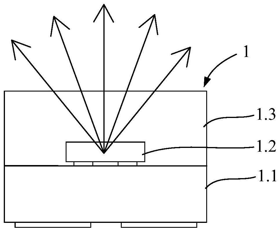
[0059] Such as Figure 4 to Figure 7 Shown is a schematic structural diagram of the first embodiment of the LED light source of the present invention. An LED light source in the present invention not only includes a light source substrate 1.1, a blue light chip 1.2, and a silica gel 1.3, but also includes a green light chip 1.4, and the green light chip 1.4 and the blue light chip 1.2 are fixed on the side of the light source substrate 1.1. The upper end, and the green chip 1.4 and the blue chip 1.2 are electrically connected to the light source substrate 1.1, the silica gel 1.3 is fixed on the upper end of the light source substrate 1.1 by molding, the green chip 1.4 and the blue chip 1.2 Packaged in the silica gel 1.3, the silica gel 1.3 protects the green chip 1.4 and the blue chip 1.2 and the parts where the green chip 1.4 and the blue chip 1.2 are electrically connected to the light source substrate 1.1. As mentioned above, the blue light chip 1.2 and the green light chi...

Embodiment 2

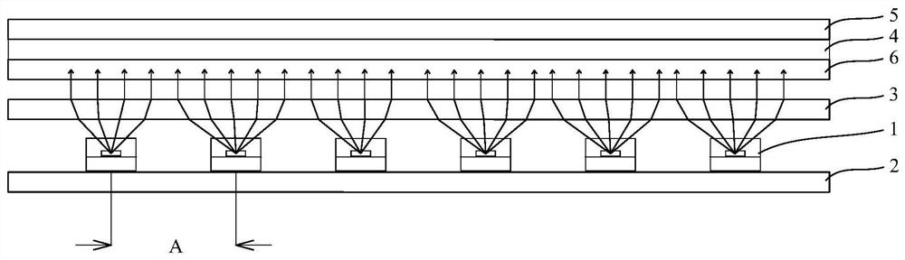
[0071] Such as Figure 9 Shown is a schematic structural diagram of the second embodiment of the LED light source of the present invention. An LED light source in the present invention, on the basis of Embodiment 1, a scattering layer 1.6 is fixedly provided on the upper end of the nano-filtering reflective coating 1.5. The scattering layer 1.6 is made of silica gel mixed with diffusion powder, wherein the diffusion powder and silica gel are physically mixed without chemical reaction.

[0072] Most of the light scattered through the silica gel 1.3 for the first time will enter the scattering layer 1.6 through the nano-filter reflective coating 1.5, and undergo secondary scattering in the scattering layer 1.6, thus making the light emitted by the LED light source 1 more uniform; At the same time, the light reflected by the nano-filter reflective coating 1.5 and the module substrate 2 will fill the gap between adjacent LED light sources 1 . Thus, by using the silica gel 1.3 mi...

Embodiment 3

[0074] Such as Figure 12 As shown, the present invention also provides a method for preparing an LED light source, which specifically includes the following steps:

[0075] S1. Brushing solder paste: Print solder paste on the entire substrate, so that the solder paste adheres to the pad position to be solidified on the entire substrate. Wherein, the entire substrate can be cut into light source substrates 1.1 with a size of 1.0mm*1.0mm, and the light source substrates 1.1 are arranged in an array.

[0076] S2. Die-bonding: Flip multiple sets of blue light chips 1.2 and green light chips 1.4 respectively on the corresponding die-bonding positions on the entire substrate, and make the blue light chips 1.2 and green light chips 1.4 corresponding to the entire substrate after reflow soldering The welding pads of the blue light chip 1.2 and the green light chip 1.4 are welded together by solder paste, so as to realize the electrical connection between the blue light chip 1.2 and ...


PUM

PropertyMeasurementUnit
beam angleaaaaaaaaaa

Abstract

The invention relates to an LED light source and a preparation method thereof and a backlight module, and belongs to the technical field of display. The LED light source comprises a light source substrate, a green light chip, a blue light chip and packaging glue. The green light chip and the blue light chip are fixedly arranged at the upper end of the light source substrate, the green light chip and the blue light chip are both electrically connected with the light source substrate. The packaging glue is fixedly arranged at the upper end of the light source substrate, the green light chip and the blue light chip are packaged in the packaging glue, diffusion powder is mixed in the packaging glue, and the diffusion powder can perform primary scattering on light rays emitted by the green light chip and the blue light chip. Compared with the prior art, the light emitting angle of the LED light source can be increased, the cost is reduced, and the service life of the backlight module is prolonged.

Description

technical field [0001] The present invention relates to the field of display technology, in particular to an LED light source, a preparation method thereof, and a backlight module. Background technique [0002] With the pursuit of the ultimate TV display effect by customers and the market, the display effect of conventional LCD TVs can no longer meet the needs of users. Therefore, TV display screens are gradually shifting from direct-lit backlight LCD screens to those with higher color purity and higher color gamut coverage. Higher efficiency, higher brightness and transition to Mini LED quantum dot displays with local dimming. [0003] Among the three quantum dot materials of red, green, and blue, the luminous efficiency and stability of red quantum dots are the highest, followed by green, and blue is the lowest. Based on this, the electroluminescent display scheme cannot be realized at this stage, that is, the display scheme that simultaneously utilizes three quantum dot ...

Claims


Application Information

Patent Timeline
Patent Type & Authority Applications(China)
IPC IPC(8): H01L25/075H01L33/58H01L33/60H01L33/54H01L33/56F21V19/00F21V13/00F21Y115/10
CPCF21V13/00F21V19/001F21Y2115/10H01L25/0753H01L33/54H01L33/56H01L33/58H01L33/60H01L2933/005H01L2933/0091
Inventor 何至年唐其勇朱弼章周波
Owner 江西兆驰光元科技股份有限公司
Why Eureka
Try Eureka